Working with the probe has significantly changed our
understanding of electrolytic capacitors,
their quality and manufacturers...
One of the most unreliable radio elements in electronic equipment has been and remains an electrolytic capacitor. The most common cause of failure is the "drying out" of the electrolyte, which leads to an increase in the ESR (equivalent series resistance) of the equivalent series resistance (ERS). When measuring only the capacitance of a "dried" capacitor, the difference with a serviceable one is practically not visible. In addition, in most cases, capacitance measurement will require removing the capacitor from the circuit, which is not always convenient, and the soldering-soldering process adversely affects the capacitors themselves.
Based on the experience of designing and operating similar devices, here is comparison of devices various types and formats for measuring and indicating the equivalent series resistance (ESR) of electrolytic capacitors.
The requirements underlying the development of our electrolytic capacitor tester - Equivalent Series Resistance Indicator:
1. Possibility to check capacitors without soldering out of the circuits.
1.1 To reduce the influence of the circuit in which the electrolyte is located, not to harm it, and at the same time to minimize its influence on the measurement accuracy, the voltage on the open probes should not exceed 200 mV (less than opening semiconductor np junctions).
2. Portability, convenience, practicality.
2.1 The device should be made in the form of a probe, because there is no need to accurately measure the ESR, a measurement error of 20 - 30% is quite satisfactory. By the way, from experience - heating an electrolytic capacitor from room temperature to finger temperature (33-35 OC) lowers ESR by an average of 1.5 times. Accurate measurement of ESR is justified only in the conditions of plants producing electrolytic capacitors, for the monitoring of products. And the reaction speed to the LED indication is much faster than to the display numbers. At the same time, in order to expand the measuring range, a logarithmic indication is preferable to a linear one. The logarithmic indication allows to cover a wider dynamic range on the same number of LEDs than the linear one.
2.2 The device must be rechargeable with an autonomy of at least 8 hours. This is enough to use the device for field work, without carrying an adapter with you on business trips, which, by the way, weighs more than the device itself.
2.3 Protection against the charge of the measured capacitor. The probe must not be damaged or damage must be minimal if the measured capacitor is charged.
3. To ensure adequate accuracy and eliminate the dependence of the indication on capacitance, a synchronous detector must be present in the circuit.
4. The measurement frequency should be between 30 - 200 kHz.
Probe - meter - indicator of equivalent series resistance (ESR, ESR) of electrolytic capacitors. Specifications of the latest version of the instrument
The device is designed to evaluate the ESR (equivalent series resistance, equivalent series resistance, ESR) of electrolytic capacitors without soldering (disconnecting) from the circuits.
AC voltage on open probes is not more than 200 mV, which eliminates the influence of external circuits on readings device, and the induced voltage will not damage external circuits.
Measurement frequency 100 kHz +- 20%
Range of the estimated ESR 0.1 - 5.0 Ohm.
LED indication with a logarithmic scale. The number of indication LEDs is 10.
The range of capacitances of the tested capacitors is from 0.1 μF or more.
When connected, it withstands the discharge of capacitors up to 50 V.
Powered by a built-in Li-ion battery.
A full charge of the battery lasts for 10 hours of continuous operation of the device.
The duration of a full charge is no more than 3 hours.
The charging control circuit is built into the device.
Charging adapter - from Nokia mobile devices of the old type (type ACP-7E 3.7V 355mA 1.3VA).
Probe - meter - indicator of ESR (equivalent series resistance, ESR) of electrolytic capacitors. Simplified design (prototype) of a device for testing electrolytic capacitors.
Simplicity of the design of the probe and efficiency in operation, has already been verified by 10 years of operating experience both in the workshop and on the road. The device for testing electrolytic capacitors proposed for repetition does not contain microcontrollers and is assembled on available common parts.
The device is designed to evaluate the ESR (equivalent series resistance, equivalent series resistance, ESR) of electrolytic capacitors without soldering (disconnecting) from the circuits.
AC voltage on open probes is not more than 200 mV.
Measurement frequency 40 kHz +- 20%
The estimated ESR range of 0.2 - 5.0 Ohm is divided into 2 subranges 0.2 - 1.0 Ohm and 1.0 - 5.0 Ohm.< br />LED display with logarithmic scale. The number of indication LEDs is 5.
The range of capacitances of the tested capacitors is from 1.0 μF or more.
When connected, it withstands the discharge of capacitors with a voltage of up to 300 V.
Power is supplied from a built-in Ni-Cd battery with a nominal voltage of 3 .6 V, 80 mAh.
A full charge of the battery lasts for 6 hours of continuous operation of the device.
The duration of a full charge is no more than 3 hours.
The charging control circuit is built into the device.
Charging adapter - from old-style Nokia mobile devices (type ACP-7E 3.7V 355mA 1.3VA).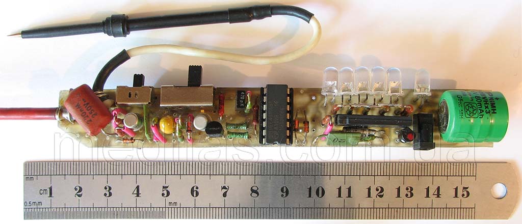
Fig.2 Appearance of the finished design of the probe - ESR indicator of electrolytic capacitors.
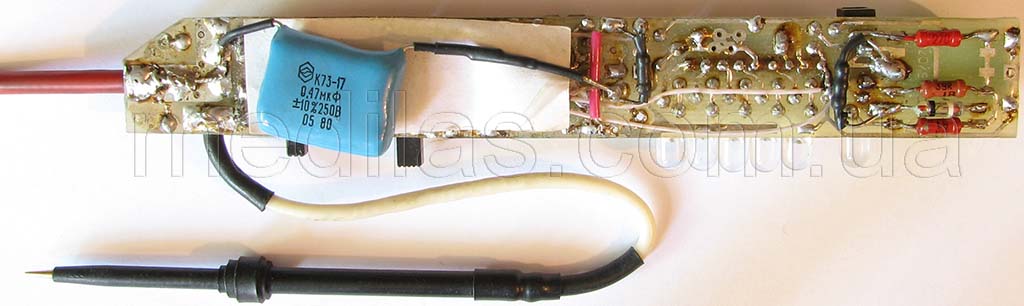
Fig.3 View of the device for testing electrolytic capacitors from the side of the printed circuit board.
Fig.4 Structural diagram of the probe - ESR indicator of electrolytic capacitors. frequency of 35-40 kHz, a limiter to prevent damage if the measured capacitor is charged, a high frequency switchable gain amplifier, a detector, an indicator, a voltage regulator and a battery with a charge circuit.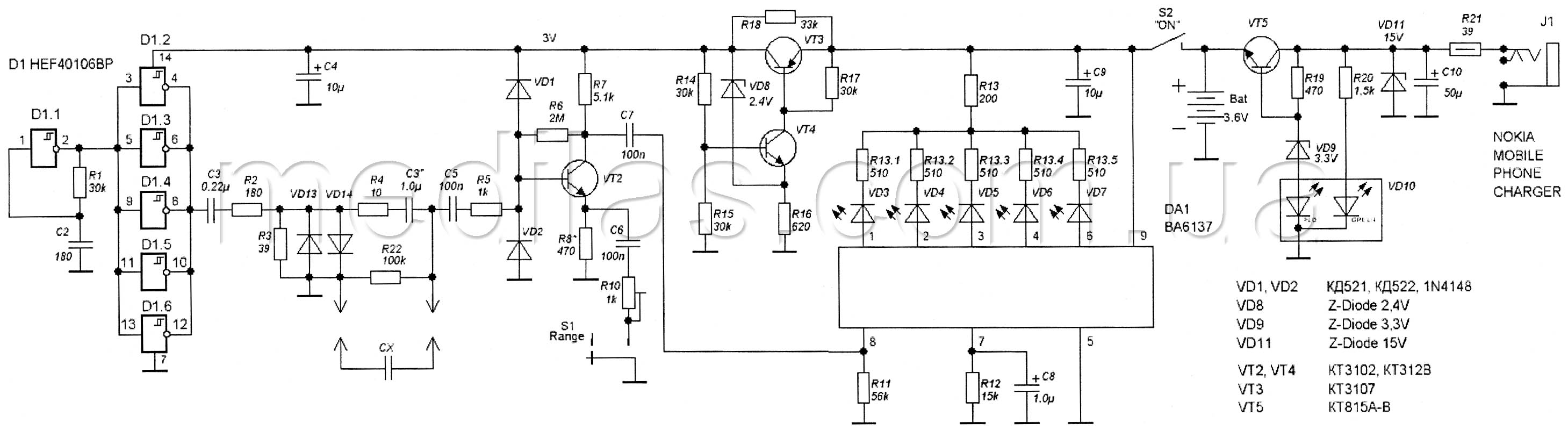
Fig.5 Schematic diagram of the probe - ESR indicator of electrolytic capacitors.
The master oscillator is made on a CMOS chip (CMOS) D1 40106 - 6 Schmidt triggers, which made it possible to simplify the circuit and include 5 elements as an output buffer.This solution made it possible to leave the output current sufficient, because of It is known that at a minimum supply voltage, the buffer properties of CMOS elements, as well as any other ones, also fall to a minimum. Resistors R2 and R3 form a divider that determines the output voltage across the open probes. Diodes VD13, VD14 protect the outputs of the D1 chip from getting voltages between the probes due to measurements of capacitors that “turned out to be” charged, or during “accidental” inclusion in the working circuit. High-frequency amplifier diodes VD1, VD2 and resistor R5 protect against similar cases.
The high-frequency amplifier is made on the transistor VT2, and serves to increase sensitivity when measuring low values of equivalent series resistance. In order to provide measurement over the ESR range of 0.2 - 5.0 ohms using a 5-LED logarithmic indicator, the range was divided into 2 sub-ranges. Switching between subbands is performed by switch S1, which changes the gain of the high frequency amplifier (UHF). The UHF gain on the sub-range 1.0 - 5.0 Ohm is approximately 5 and is regulated by the selection of R8, and on the sub-range 0.2 - 1.0 Ohm it is approximately 25 and is regulated by a miniature tuning resistor (trim) R10. With the same resistor, in the process of adjustment, we achieve alignment of the subranges.
The indicator is made on the DA1 BA6137 chip (complete direct analogues of NTE1866, KA2285B, LB1423N, AN6884, GL1223), which is a driver of 5 LEDs. The microcircuit includes an active amplitude detector, a DC amplifier, a set of comparators and LED control switches with current limiters. The chip provides a logarithmic level indication. Resistor R13 is designed to reduce the level of consumption by the LEDs when the probes are not connected and all the LEDs are on.
Now a few words about choosing the operating frequency of the device. These microcircuits are designed to indicate the level of an audio frequency signal and contain an active amplitude detector. At least with the BA6137 chip, at input frequencies above 40 kHz, there was a discrepancy between the signal level and the number of on / off LEDs. For example, at a frequency of 45 kHz and ESR = 1 Ohm, only 1 LED lights up, ESR = 1.8 Ohm - 2 LEDs (that's right), and if ESR = 5.0 Ohm, everything that corresponded to ESR < 1 ohm, which will eventually lead to the definition of a faulty capacitor as a good one. On the other hand, in order to reduce the effect of capacitance on the readings, it is advisable to choose a higher frequency (100 - 200 kHz). Therefore, the operating frequency must be selected as high as possible, at which the compliance of the instrument readings is maintained. To calibrate and check compliance with the level scale, non-inductive resistances, for example, the MON type, can be used as an ESR source. The advantage of such a regulator circuit is a high stabilization factor and, unlike many integrated regulators (voltage regulators), it will not give an output voltage if the input falls below the level necessary to provide a given output voltage (UVLO under voltage lock out function). In practice, the device will not turn on and the indicator will not light up if the battery voltage drops below 3.3 V.
The device uses a nickel - cadmium three-cell battery 3.6 Volt 80 mAh. Since these batteries are unpretentious, the charging circuit does not differ in complexity. A charge voltage limiter is assembled on the VT5 transistor, limiting it to 4.5 V.
The device is assembled on a 140 x 18 mm printed circuit board (probe format). Another advantage of this design is that there is no need to be smart with the probes - after all, very strict requirements are imposed on their design and quality. In our probe, the probes are made from a piece of rod with a diameter of 2.0 - 2.2 mm for high-temperature soldering (lok). The active probe is 50 mm long, passive - 100 mm.
Adjusting a properly assembled device is carried out in the following sequence:
- Disconnecting the battery.
- The voltage control on the VT3 collector is within 3.0 - 3.1 Volts at an input voltage of 3.6 - 4.5 V, if necessary, set by selecting R14 and / or R15.
- We connect the voltmeter to the VT3 collector, and the regulated power supply to its emitter. Starting from a source voltage of 2.0 V, we gradually increase it to the point where the stabilizer is turned on (observed by an abrupt increase in voltage on the VT3 collector). The voltage at the VT3 emitter should be in the range of 3.3 - 3.4 V. You can lower the turn-on voltage by slightly lowering R18. To measure the voltage of the switch-on point again, it is necessary to set the voltage on the regulated power source below 2.0 V, turn it off, pause until the stabilizer resets, turn on the source and increase the voltage again, controlling the voltage on the VT3 collector. This order is because the stabilizer has a trigger property.
- Subsequent tuning can be carried out with the battery connected and charged.
- According to the criteria described earlier, we select the generator frequency with resistor R1.
- Set S1 to the left (according to the diagram).
- Connect a 4.7 ohm resistor to the probes and, choosing R8, ensure that 4 of the 5 indicator LEDs are on.
- Set S1 to the right (according to the diagram).
- Connect a 0.8 ohm resistor to the probes and, turning the R10 slider, again ensure that 4 of the 5 indicator LEDs are lit.
This setup can be considered complete.
In general, it is worth noting that correctly assembled probes with R10 replaced with a constant 220 Ohm worked satisfactorily even without adjustment.
Ways to upgrade the probe prototype - ESR indicator (equivalent series resistance)
About 10 years have passed since the release of the first version of the probe (prototype), the element base has changed during this time, so we decided to describe several directions in which we modernized our working samples that we are now releasing.
- Using a synchronous detector, get rid of the dependence of the instrument readings on the capacitance of the capacitor being tested. The use of a synchronous detector imposes a condition - the absence of phase shifts in the measurement circuits. Appropriate adaptation of the measurement circuits led to a decrease in the threshold voltage on the measured capacitor, at which the input circuits (generator and limiter) can fail. In other words, the circuits connected to the measured capacitor become more "gentle". Another less significant aspect is the introduction of a function for measuring (estimating) the capacitance of the measured capacitor into the circuit becomes more complicated. But, as practice has shown, the feasibility of such a function is quite low. Therefore, the function of measuring the capacity of the electrolyte was excluded from this already at the prototype stage, where it was implemented by fairly simple means (by adding one capacitor and one switch to the circuit).
- Using a lithium-ion Li-ion battery. This will reduce the weight and dimensions of the device and increase the battery life. This will require the use of a battery management processor.
- You can also replace the stabilizer on discrete elements with an integral one. You will have to choose an integral stabilizer with the UVLO (under voltage lock out) function, or organize it in other ways.
In a word, there is no limit to perfection....
Summary. The assembled probe - equivalent series resistance meter turned out to be one of the most requested devices in the workshop, which is not a pity to spend time and effort on development and assembly. After its appearance, no one is looking towards a professional digital ESR meter. At first, they rechecked the readings of the assembled probe - the meter, then they threw it far on the shelf. Moreover, when the question arose that one probe is clearly not enough, we decided to again develop a more advanced design on a modern element base. Only the format of the device remained from the old version: a small-sized hand-held battery probe - an indicator on LEDs with an external charging adapter, where all additional functions were removed in favor of reducing the size and accuracy of measuring ESR and decoupling the dependence of readings on capacitance.
September 14, 2014, Odessa, UKRAINE