

")
")
Cardiosignal generator (ECG simulator) is designed to test and repair cardiographs, Holter monitors and cardioblocks of resuscitation monitors and defibrillators. The ECG signal generator is a portable device powered by a built-in lithium rechargeable battery.
It is possible to connect cables with 4 mm plugs with a spring (banana), DIN3.0 (Pro version) and "button" or "clip" contacts.< br />The cardiograph tester generates square waveforms with pulse width = pause duration (duty cycle = 2), and a signal that simulates the work of the heart (cardiac-like signal).
The device can be used for:
1. Checking the amplitude of the recording from all leads. To do this, a U-shaped signal with an amplitude of 1 mV and a frequency of 1 Hz (60 beats/min) or 2 Hz (120 beats/min) is applied to the selected group of leads.
2. Checking the general functionality of electrocardiographs, as well as for simulating a patient when checking stress systems. The ECG generator generates a cardio-like signal with a frequency of 1 Hz (60 bpm) in all leads simultaneously.
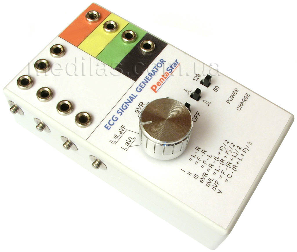
Fig. 1 Сardiosignal generator (ECG simulator).
The main characteristics of the device for checking cardiographs (cardiosignal generator):
Square-shaped signal with an amplitude of 1.0 mV, and a frequency of 1 Hz (60 bpm) and 2 Hz (120 bpm).
The signal simulating the work of the heart has an unnormalized amplitude (of the order of 1.0 mV) and a frequency of 1 Hz (60 bpm).
Output modes - a signal to a selected group of leads or a signal to all leads simultaneously.
Signal frequency stabilized by quartz, amplitude - built-in voltage stabilizer.
The ECG simulator is portable, powered by a built-in lithium polymer battery.
Charging is done via a mini-USB connector.
The time to fully charge the built-in battery is 2.5 -3 hours.
The charging process is controlled by the built-in controller, overcharging is excluded. The charging status is monitored by an LED.
A fully charged battery is enough for at least 48 hours of continuous operation of the cardiac signal generator.
Device dimensions: length 133 mm, width 80 mm, height 54 mm.
Operating mode - can work around the clock without interruption.
The weight of the cardiosignal generator without accessories is 170 g.
Operating temperature range 0 - +50 OC
Storage temperature range -40 - +50 OC
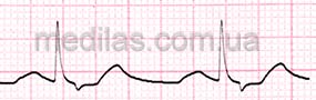
Fig. 2 Waveform in the mode of generating a cardio-like signal (ECG simulator).
A simple small-sized device for checking cardiographs (cardiosignal generator) without a microcontroller and ROM (prototype).
When developing the cardiac signal generator (a device for testing cardiographs), the task was to provide acceptable performance with maximum simplicity and reliability of the design. As long-term practice has shown, the device must be portable (small-sized, light), powered by a built-in battery and have contacts for connecting both cardiographs and heart monitors. For most practical cases, a rectangular output signal with several fixed amplitude and frequency values is sufficient. For ease of repeating the design, we decided to do without a microcontroller. As the practice of operation later showed, a series of signals generated by the microcontroller, qualitatively simulating heart signals, is necessary only to check the automatic diagnosis by cardiographs, and to demonstrate the work to the client. And, for example, to check the stress test complexes, the signal generated by the proposed ECG simulator is enough.
Based on these requirements, the circuit of the cardio signal generator (ECG simulator) version 1.0 (prototype), shown in Fig. 3, was developed and tested. Hereinafter, when downloading, the pictures will have their original size.
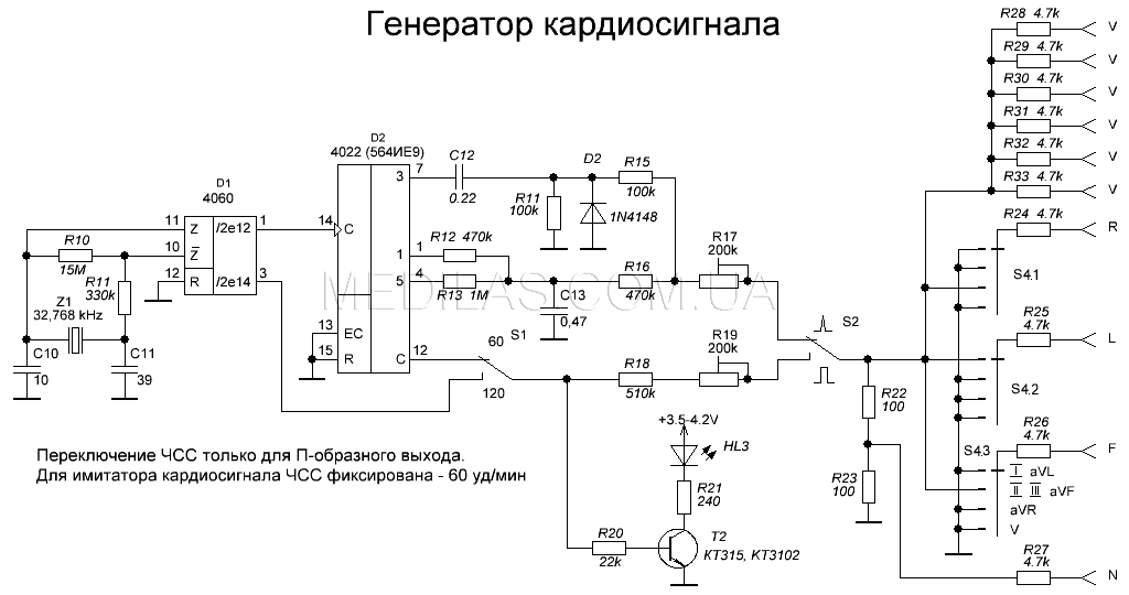
Fig. 3 Scheme of the prototype (version 1.0) of a simple cardiac signal generator.
Key Features of the Cardiograph Tester:
- The circuit provides an output signal amplitude of 1 mV.
- HR (heart rate) is switched only in 1 Hz (60 bpm) and 2 Hz (120 bpm) rectangle shaped pulse mode.
- In simulation mode (generation of a cardio shape signal Fig. 2), the frequency is fixed at 1 Hz (60 bpm).
- It takes 2.5-3 hours to fully charge the rechargeable battery.
- Continuous operation time of generator - up to 48 hours.
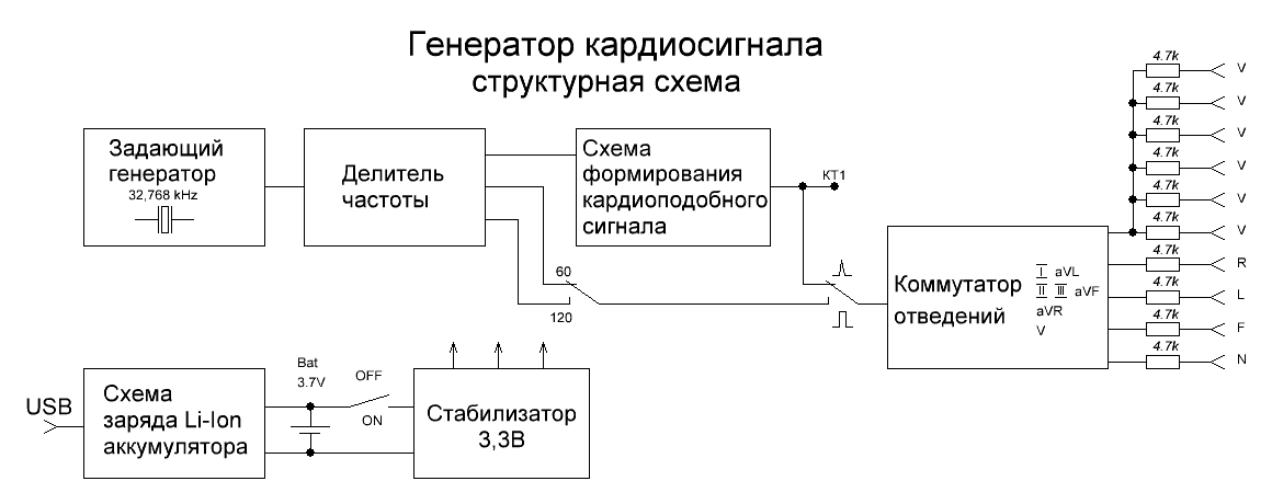
Fig. 4 Structural diagram of the cardiac signal generator.
CMOS chips are used to keep power consumption to a minimum. The crystal oscillator and divider are assembled on the elements D1, Z1, R10, R11, C10, C11 ... To improve performance, a simple cardio signal shaper was implemented in just one chip D2. For simplicity, heart rate switching is performed only for the rectangle shaped signal. The HL3 LED is the only one of the LEDs that is powered by a rechargeable battery and is the most current-consuming element. Therefore, it is not supplied with direct current, but with rectangle shaped pulses, which made it possible to halve its power consumption and ensured control of the maximum number of functions:
- power-on indication;
- U-shaped output heart rate indication;
- indication of the operability of the crystal oscillator and frequency divider.
Variable resistances R17 and R19 regulate the output amplitude of the signal in the mode of the simulator, respectively, and in the mode of U-shaped pulses.
applied mechanical switch S4. Resistors R24 - R33 are approximately comparable to the resistance of the human body. With them, by recording distortions, such malfunctions as leakages to the screen in lead cables and in protective diodes of the input circuits of cardiographs and heart monitors are detected. The power supply circuit of the cardiosignal generator is shown in Fig. 5.
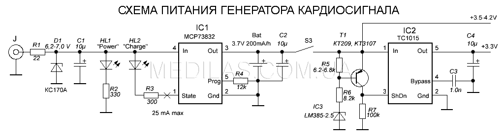
Fig. 5 Cardiac signal generator power supply circuit.
The circuit is powered by a 200 mAh lithium polymer 1-cell battery with an operating voltage of 3.7 V through a voltage regulator on the IC2 chip, the output of which is a voltage of 3.3 V. The circuit on IC3, T1, R5 - R7 serves to prevent IC2 from turning on if the battery voltage drops below 3.4 V, which prevents over-discharging of the battery and its premature loss of capacity, as well as a mismatch in the output voltages of the cardiac signal generator due to a voltage drop of +3.3 V.
Application lithium - polymer battery required the introduction into the controller circuit of its charge and state on the IC1 chip, resistors R3 and R4. The D1, R1 circuit is needed to prevent the failure of the IC1 chip if several chargers with different characteristics are used. If you plan to use the recommended charger for old-style Nokia mobile phones (ACP-7E 3.7V 355mA 1.3VA type), or charge from USB, then this circuit can be omitted. The printed circuit board below is wired for a charger connector for Nokia mobile phones type ACP-7E 3.7V 355mA 1.3VA (old version).
The cardio signal generator (ECG simulator) is assembled on a printed circuit board made of one-sided foil fiberglass 70 x 50 mm in size (Fig. 6). The semi-circular notch serves to accommodate the S3 lead switch.
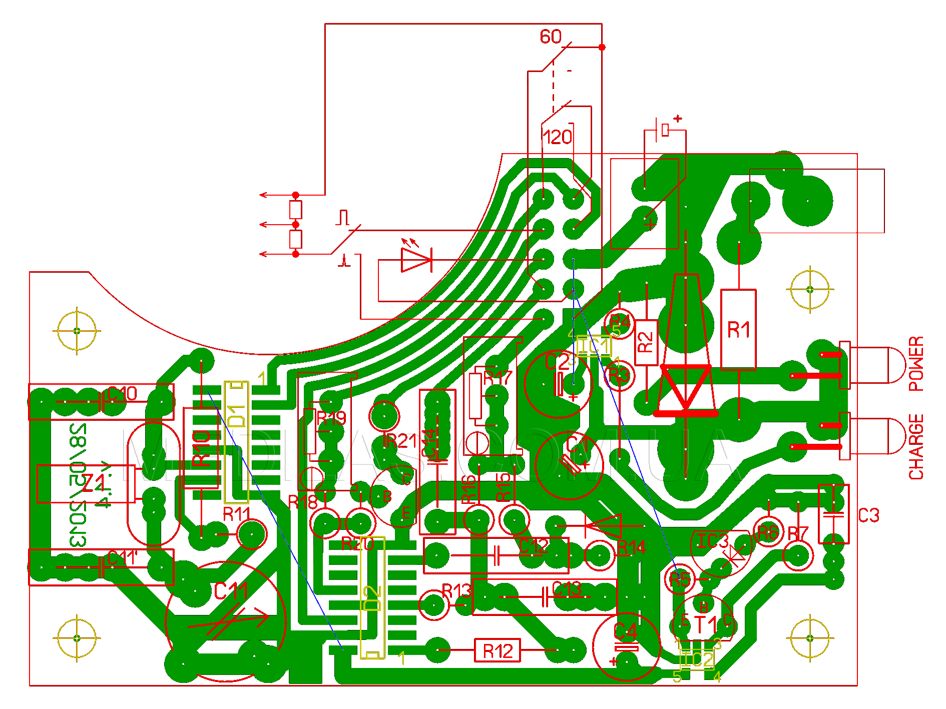
Fig. 6 Printed circuit board of the cardiac signal generator (ECG simulator).
A properly assembled circuit will work immediately after power is applied, but to obtain compliance with all characteristics, it is necessary to carry out a simple adjustment.
Establishing a power supply circuit is reduced to selecting a resistor R5 so that when the power is turned on by switch S3, the supply voltage is +3, 3 V appeared only if the voltage on the battery is greater than or equal to 3.4 V.
Trimming resistors R17 and R19 achieve the specified voltage amplitude at the outputs of the cardio signal generator.
03 September 2014, Odessa, UKRAINE