

")
")
The practical design of a simple and effective charging station, easily and quickly assembled at home from inexpensive, common parts, is described
The task was to quickly assemble a simple and inexpensive charging station with automatic recharging from the mains, at minimal cost, quickly and adaptable to any type of battery. The condition was to create the most universal platform, subject to various retrofits and operated according to the principle “plug the cord into the socket and don’t worry about keeping the accumulator charged.” Also, a condition was maximum efficiency when powered by batteries. In other words, it was necessary to obtain the maximum effect for a minimum of money and time.
To simplify and speed up assembly, it was decided to assemble the charging station using commercially available ready-made modules and garage trash.
The circuit and design of the specified charging station described is designed and executed based on the following conditions:
- The presence of a large number of Li-Ion 18650 battery cells asking for recycling
- Possibility of operation from both internal and external batteries
- External battery input voltage range 9-18 volts (omnivorous)
- Automatic charging from 220 volt mains, charging only the internal accumulator
- USB output 5 volts, 3-5 A
- Output to laptop 19 volts 3 A
- Adjustable output to a soldering iron (for power adjustment) 150 - 260 volts DC 0.3 A (optional)
- Since there is an external battery 12 volt 100 A/h and an inverter, the formation of ~ 220 volt charging station is not required
Availability of a sufficient amount of garage scrap (getinaks panels, hardware, old domestic radio components, wires, corners, etc.) To speed up assembly and reduce the cost of design - maximum use of garage trash and disassembly (wires, studs, nuts, textolite, diodes, transistors, connectors, etc.)
The appearance of the charging station without the top cover is shown in fig. 1.
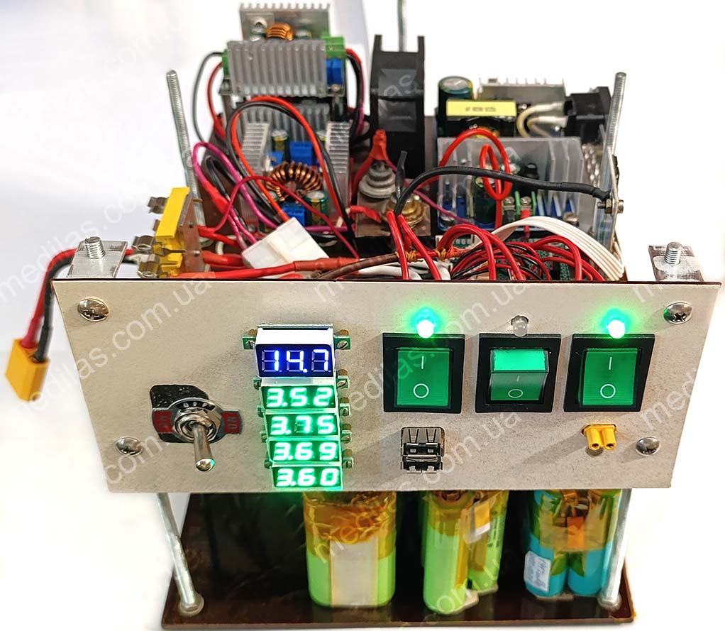 Fig. 1 Charge station
Of course, the needs in each case may be different, for example, power for a soldering iron is not required, but power for 3-5 laptops is needed with a voltage of not 19 volts, but 21 volts. Therefore, it is more important to be guided by ideas and implementation principles, rather than copy a specific design. But, to speed up the repetition of the design, if somebody asks us, we will also include the drawings. The design was based on the principle of powering devices with their specific voltages, rather than converting them to 220 volts, which corresponds to the principle of the highest efficiency when powered by batteries. This efficiency results in much longer battery life. Another topology based on a purchased UPS (Uninterruptible Power Supply) is MUCH less economical and costs more, although it is easier to implement.
Description of the electrical circuit diagram of the charging station
Description of the electrical circuit and operating principle of the charging station
The on-line principle was chosen, when consumers are powered through converters from batteries, and the batteries are charged and the voltage on them is maintained according to the presence of voltage in the mains. It is this construction topology that has maximum efficiency when powered by a accumulator and satisfies the “plug and forget” operating principle. This design principle allows us to consider such a system as a flexible and universal platform for building an energy supply system for home and office. Another important advantage is the ability to build and easily adapt to any type of battery. For example, one of the options was built and worked perfectly on a gel battery with one closed can! This “unpretentiousness” to batteries allows you to use (after selection) even those that are left in workshops for repacking battery packs, and, believe me, in each such service center, every working day there are 10-100 cells that have lost their capacity, but are still suitable. Such elements can be found in workshops for repacking electric vehicle batteries (electric cars and scooters, hoverboards, etc.), repairing laptops and cordless power tools (screwdrivers, etc.). Such elements and batteries are sold cheaply even on the radio market. In other words, a battery from the same UPS, but connected to an on-line circuit, can power the same consumers much longer than when working in its own UPS. This is explained by the fact that converting from 12 volts to 220 AC, and then back to 5, 12 and 19 volts is MUCH less economical than converting similar DC voltages.
The charging station diagram is shown in fig. 2.
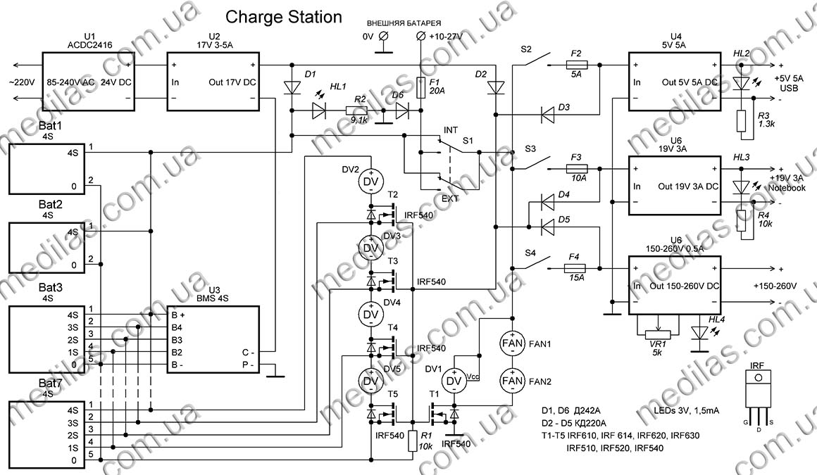 Fig. 2 Charge station schematic diagram
The battery packs are charged by a DC power supply U1, which has a 24 volt output of 3-6 amperes of stabilized or unstabilized voltage. To speed up assembly, you can use a ready-made purchased power source, and to reduce the cost, you can get by with a transformer with a diode bridge and a smoothing capacitor (see Fig. 11 Diagram of a simplified charging station). The charging mode is formed by a step-down converter U2, on which it is necessary to adjust the final charge voltage and current before starting the operation.
The step-down converter used as U2 is shown на fig. 3
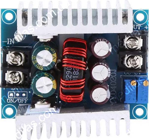 Fig. 3 Step down DC-DC converter in LM25116, Uin-6~40V, Uout-1.2~36V, 20A, with voltage and current adjustment
This two-stage circuit provides modularity and does not demand the stability of the output voltage of U1 unit. It is assumed that the charging circuit is constantly connected to the mains (even a switch is not provided) and recharges the batteries as needed. The accumulator charging circuit also includes a diode D1, which is designed to eliminate battery discharge through the U2 converter when there is no mains power.
Toggle switch S1 is designed to switch the external and internal batteries and must be designed for sufficient current.
Diode D6 together with fuse F1 forms system protection against polarity reversal.
Voltmeters DV2-DV5 are designed for more careful monitoring of voltages in battery pack sections. Voltmeter DV1, let's call it "main", shows the voltage that is supplied to the consumer converters. To ensure that the voltmeters are turned on only during operation or charging, a circuit consisting of T1 - T5, R1, D2 - D5 is provided. The circuit works as follows: When the system is disconnected from the mains and no consumer converter is turned on, the field-effect transistors are closed because there is zero voltage at their gates, thanks to R1. If switches S2 - S5 turn on at least 1 consumer, or a charging voltage appears at the output of the converter U2, then the transistor-opening voltage is supplied through the corresponding diode D2-D5 and the voltmeters are turned on.
In addition to the voltmeter DV1, transistor T1 also includes 2 12-volt fans FAN1 and FAN2, connected in series. This inclusion will reduce the noise level and current consumption of the fans and makes it possible to do without a voltage stabilizer supplied to them.
Consumer converters are switched on via fuses F2 - F4 by switches S2 - S5. The number and configuration of converters correspond to the requirements for a specific charging station, for example, most users do not need a soldering iron converter, but sometimes it is necessary to connect a 12 volt DC inverter to 220 volt 50 hertz. Such a charging station was made with 3 step-down converters, adjusted to an output of 13.5 volts 10 - 12 amperes, and fed an inverter with a pure sine wave output. Why 13.5 volts and not 12? Both the converters and the inverter with this setting have greater efficiency, and the maximum input voltage of the inverter, according to its instructions, was 14 volts.
Batteries used in this charging station
When working with batteries, you should follow safety precautions. To avoid explosion, fire, chemical poisoning, and other negative consequences, it is strictly forbidden to short-circuit cells and batteries, overheat, overload with current more than permissible, disassemble, or exert destructive mechanical influence. This is especially true for Li-ion and Li-pol cells and batteries.
It was decided to organize the battery cells into battery packs of 12 pieces, 4 in series (4S) and 3 in parallel. Because the selection occurred quite slowly (4 elements that turned out to be suitable were driven in the Opus-3100 for 4 - 6 hours), the selection of elements and recruitment into batteries continued even after the assembly of the charging station. But in general, the dimensions of the 1st floor made it possible to accommodate 7 such battery packs, i.e. 84 cells in total. Considering that the average capacity of the selected elements is about 1700 - 1800 mAh, the energy of such a battery pack will be about 500 Wh.
We had at our disposal 2 4S battery packs made of 12 Li-Ion elements, with their own built-in BMS (Battery Management System) module controller, each tired, but still capable of something, and it was decided to use them as is (in the diagram Bat1 and Bat2). This is also due to the duration of the selection of individual elements. The rest had to be taken apart and each element had to be selected for “professional suitability”.
Fig. 4 Battery packs used in the described charging station
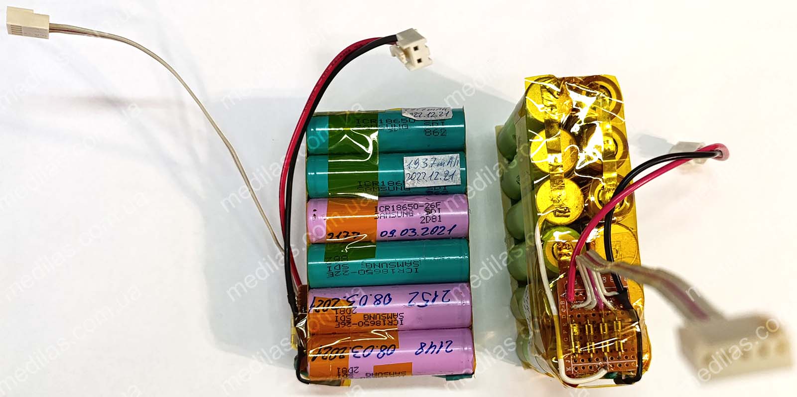 Fig. 4 Rechargeable battery packs used in the charging station
* the number before S means the number of elements connected in series.
The battery packs were connected in parallel, the intermediate connections of the battery packs were also taken out and connected in parallel and finally connected to the BMS (Battery Management System) controller U3, the use of which is mandatory with lithium batteries. Its purpose is to protect the batteries from overcharging and overdischarging, which in turn affects the accumulator life and safety of use. In case of detection of voltage exceeding 4.2 volts (overcharge) on at least one of the 4 groups of parallel wired cells, the BMS controller breaks the battery charging circuit. If the BMS controller detects a voltage drop below 2.7 volts on at least one of the 4 groups of parallel wired cells (over-discharge), the BMS controller will break the battery load circuit. This BMS controller, like most others, if the protection is triggered, breaks the negative pole of the batteries.
A schematic of each repackaged battery pack is shown in fig. 5.
 Fig. 5 Circuit of the rechargeable batteries used in the charging station
Each battery packs has 2 outputs - a power output with 2 contacts, female, and a balancing output with 5 contacts, female.
Rechargeable battery selection
One of the distinctive features of the proposed circuitry is the ability to work with any type of accumulator with a voltage from 9 to 18 volts. At least in this voltage range tests were carried out. So, for example, to check the operation of the charging station from an external battery, we connected a car battery with one shorted can.
But there is one essential condition: if we assemble, say, a battery pack from several batteries, they must be of the same electrochemical system. That is, it is in no way possible to include in parallel, say, a battery pack of Li-ion cells with a battery of lead chemistry, or with a battery on LiFePO4 cells. If an electrochemical system is chosen, e.g. Li-ion or Li-pol, then all cells of all battery packs connected in parallel must be of this electrochemistry. This limitation can be overcome by switching between internal and external batteries because these batteries will not "meet" each other in parallel. For example, in the described charging station the internal battery pack is 4S Li-ion, and as an external accumulator we tried both a lead-acid car battery with 1 closed bank and 6S LiFePO4 (18 volts) and everything worked perfectly.
There is an opinion on the Internet that 6S lead electrochemical batteries (lead-acid, gel, or AGM), 4S LiFePO4, and 10S NiCd and NiMH batteries have approximately the same voltage, about 12 volts, but we still do not recommend connecting them in parallel as there are some differences in their charging and discharging curves.
Another condition is that, as mentioned above, Li-ion, Li-pol, and LiFePO4 cells must be connected via a BMS (battery management system) controller. As already mentioned, Li-ion, Li-pol, and LiFePO4 cells can be "found" in workshops where batteries for notebooks and personal electric transport (electric cars, electric scooters, gyroscooters, etc.) are repacked. These, as well as NiCd (nickel-cadmium) and NiMH (nickel-metal hydride) cells could be found in power tool repair shops. It is essential to check the elements obtained in this way for their "professional suitability", i.e. to select them at least according to their capacity and preferably also according to their internal resistance.
Description of the charging station design
The design of the charging station was chosen to be two floors, with battery packs on the first floor, and all electronics, switching, and indication on the 2nd floor.
The appearance of the electronics compartment without the top cover is shown in fig. 6
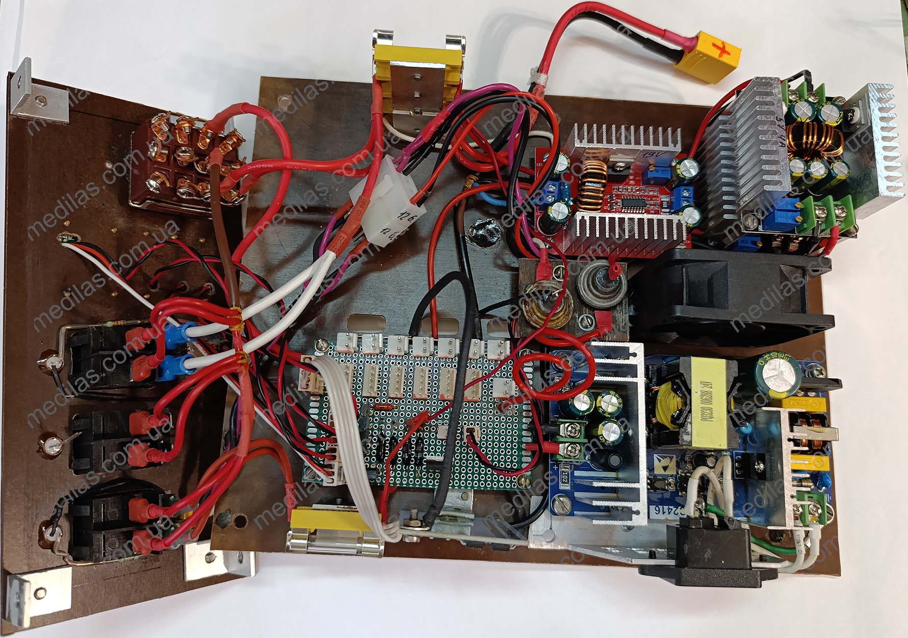 Fig. 6 External view of the electronics compartment of the charging station
The appearance of the front panel is shown in fig. 7
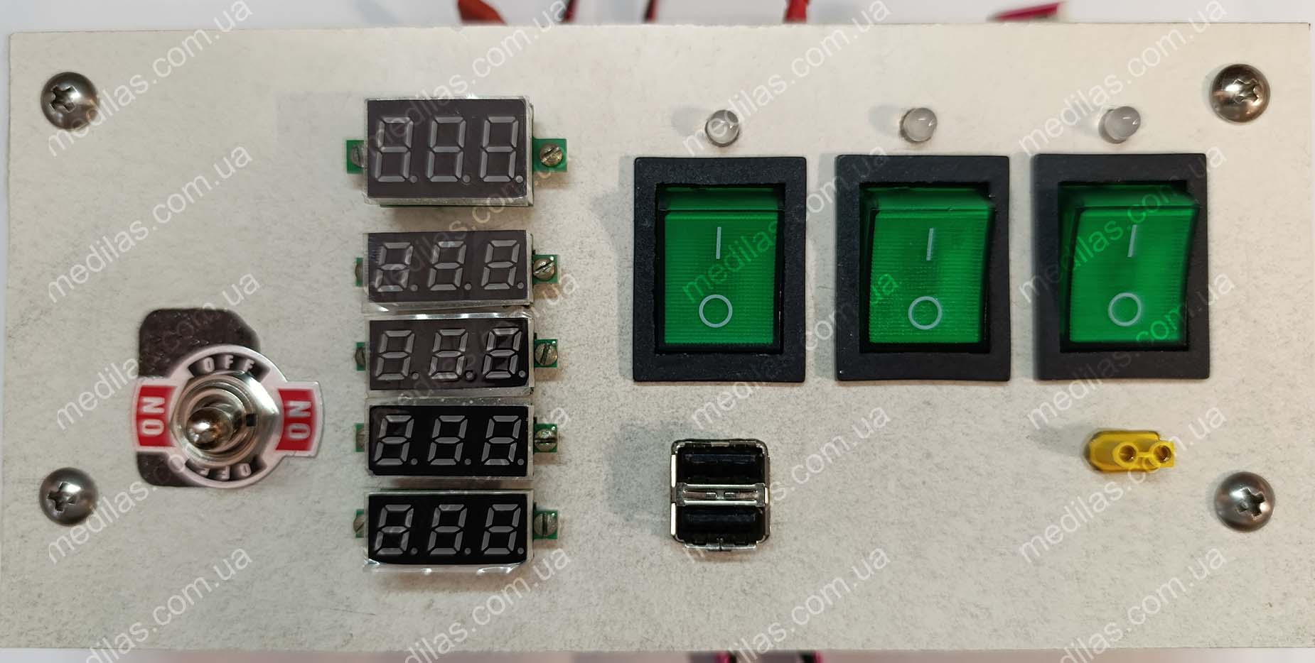 Fig. 7 Front panel appearance
All battery pack terminals are connected on the 2nd floor in parallel on a circuit board, on which a circuit with T1-T5, D2-D5, and R1 is also assembled. The entire design is made using connectors, suggesting modularity. Diodes D1 and D6 are quite powerful, mounted on a separate rectangular piece of getinax. All fuse holders are assembled on brackets at the edges for easy monitoring and replacement of fuses.
The battery elements were collected from tanks for used batteries, which were not handed over to the collection point due to lack of time. Sometimes it is useful to collect used batteries for recycling instead of stupidly throwing them in the trash). Of about 400-450 Li-Ion elements of the 18650 format, the 60 best were selected by capacity and assembled into 5 blocks of 12 pieces at 14.8 volts. Another 2 battery packs were in relatively working condition and had their own built-in BMS controllers. The selection was carried out by a charging and testing device Opus BT-C3100, powered directly from a 12-volt battery to ensure uninterrupted operation. A 10A 85-degree thermal fuse is installed inside each block. (not shown in the general diagram). Despite the selection of elements, a significant scatter of characteristics was observed both in capacity and internal resistance. Therefore, it was decided to connect all the corresponding elements of each block in parallel. This idea arose at the selection stage, so elements were selected into blocks so that an element with a lower capacity would be parallel to an element with a larger capacity. Since the charge-discharge currents are relatively small, it was decided to neglect the selection based on internal resistance.
Recommendations for used parts
- To reduce the cost, the 24V 6A mains open-frame power supply WX-DC2416 could be replaced with a circuit with a transformer with a diode bridge and a smoothing capacitor (see Fig. Diagram of a simplified charging station). In this case, the transformer must have a power of at least 150 watts and an output voltage of 17-25 volts. It is advisable to install rectifier diodes at a current of at least 10A, for example from the ancient SSSR D214A, D215A, D242A, D243A, D245A.
- The BMS (Battery Management System) controller is available in online stores by searching for “BMS controller 3-5S for Li-Ion batteries with balancing.” Must be configured for 4S battery before installation. The configuration consists of installing (soldering) jumpers 1 and 4 and removing jumpers 2 and 3 (if installed), see fig. 8
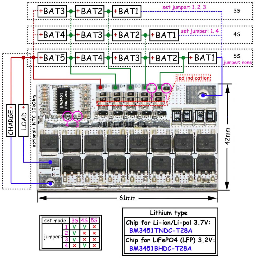 Fig. 8 BMS controller 3-5S for lithium batteries with balancing
Of course, if you have lithium-iron-phosphate (LiFePO4) cells, then you need to take a BMS controller specifically for them. The controllers differ only in the type of microcircuit. For Li-Ion and Li-Pol there is BM3451TNDS-T28A, for LiFePO4 there is BM3451BHDS-T28A, it is important not to confuse them.
- The step-down converter U4 is the same as U2, and can be found in online stores by searching for “Step-down module DC-DC 20A 6~40V, 1.2~36V with current and voltage regulation.” It's preliminary setting to at least the output voltage is required. The appearance of the applied step-down converter is shown in fig. 3
- The U5 boost converter can be found in online stores by searching for "TL494 400W Boost Converter with Voltage and Current Regulation". It's preliminary setting to at least the output voltage is required.
The appearance of the applied boost converter is shown in fig. 9
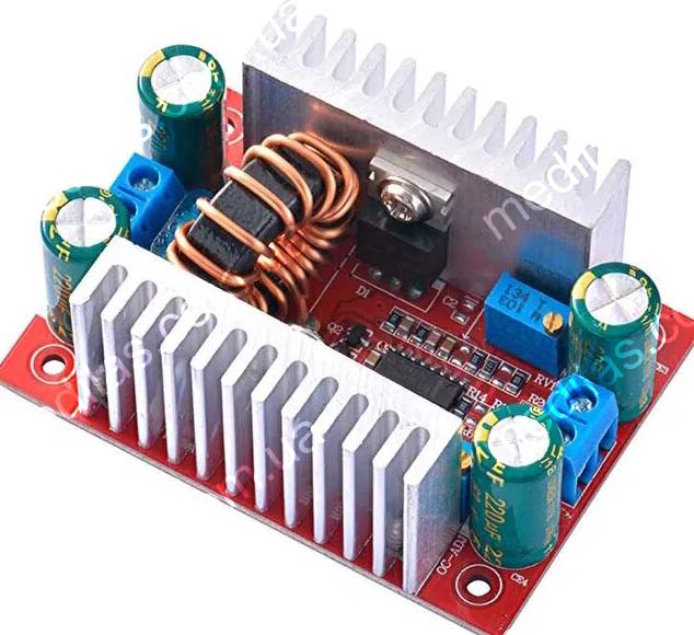 Fig. 9 Step up DC-DC converter in TL494, Uin-8.5~50V, Uout-10~60V, 400W, with voltage and current adjustment
- All field effect transistors can be used IRF510, IRF520, IRF540, IRF610, IRF614, IRF620, IRF630 and many others. There is no need to use all of the same types; differences are possible. At the charging station, in the photo, BS170 is generally used because it came to hand.
- As a battery switch, S1 must be used with sufficient switching current, for example, a KN-402 toggle switch or a KCD7-302 key switch, connecting all groups in parallel.
- Protection diode D6 for a current of at least 10A, for example from the ancient times of the USSR D214A, D215A, D242A, D243A, D245A. No need to put it on the radiator.
- The charging diode D1 is needed to automatically turn on the digital voltmeter DV1 with fans, and also to ensure that the batteries are not discharged through the charging converter U2. If it is excluded, then during a loss of 220V mains voltage, the battery will be additionally discharged through output U2. It is better to choose a diode from the Schottky series; it has a lower forward voltage drop, with a maximum voltage of at least 30 V and a maximum current of 10-40A (preferably more). If you select a diode from the ancient D214A, D215A, D242A, D243A, or D245A, then the output voltage of the charging converter U2 should be about 17.2 - 17.4 volts, if it is a Schottky diode, for example, 30D40PT, 30CPQ060, PBYR1540CT, PBYR1540CT, STPS2045CT, then The output voltage of U2 in the unloaded state should be about 17.0 volts. If the charging current is less than 5 amperes, it is not necessary to place the diode on the radiator; if it is 5-10 amperes, then the diode must be placed on a small radiator, which can be an aluminum plate with a thickness of 1 - 4 mm and a surface area of 30-100 cm square. The greater the charge current, the larger the surface area of the radiator.
- Diodes D2 - D5 - low-power (signal), 1N4148, KD220, KD223, KD509, KD510, KD513, KD521, KD522 with any letters.
- 12-volt fans from old computer power supplies, preferably identical ones.
| Ориентировочные цены на комплектующие в ноябре 2022г. | ||
|---|---|---|
| Сетевой бескорпусный блок питания на 24В 6А WX-DC2416 | 380 грн. | 1 шт. |
| Понижающий преобразователь с регулировкой напряжения и тока | 180 грн. | 2 шт. |
| Повышающий преобразователь на TL494 (для выхода на 19 В) | 220 грн. | 1 шт. |
| BMS (Battery Management System) контроллер 3-5S с балансировкой | 80 грн. | 1 шт. |
| Цифровой вольтметр высотой цифр 0,28'' | 40 грн. | 4 шт. = 160 |
| Цифровой вольтметр высотой цифр 0,36'' | 55 грн. | 1 шт. |
| Разъёмы XT-90 папа-мама | 50 грн. | 1 набор |
| Разъёмы XT-30 папа-мама | 10 грн. | 1 набор |
| Тумблер KN-402 (для переключения аккумулятора внутренний - внешний) | 150 грн. | 1 шт. |
| Клавишный выключатель выходов | 15 грн. | 3 шт. |
| Термопредохранитель 10 А 85 град. | 10 грн. | 5 шт. |
| Услуги почты около | 170 грн. | |
| Наверняка что-то забыл, поэтому закладываю ещё 170 грн (а, скорее для ровного счёта) | 170 грн. | 1 шт. |
| Всего | 1900 грн. | |
Getinaks panels, studs, nuts, etc. from garage scrap. The wires are from old computer power supplies, a diode, a switch, plugs, and connectors from disassembly, but if they are not there, then they are mere trifles.
Preparing for assembly
Before assembly, you should preconfigure the BMS controller U3, charging converter U2, and output converters U4 and U5.
- Preparation of the BMS controller U3 consists of installing and removing jumpers 1-4 in accordance with the number of battery cells of the charging station connected in series (for the described charging station this is 4S), see fig. 8. A BMS controller is not needed if lead-based batteries (lead-acid, gel, or AGM), as well as NiCd and NiMH are used. For LiFePO4 and Li-ion - Li-pol, a corresponding BMS controller is required.
- The charging converter U2 is configured depending on the batteries used.
Its output voltage is set approximately from the calculation (final charge voltage per element)*(number of elements connected in series (quantity S))+(voltage drop across diode D1). For most batteries, the final charge voltage per cell for Li-ion and Li-pol = 4.2 volts, for LiFePO4 = 3.7 volts, for NiCd and NiMH = 1.38 volts, and for lead chemistry (lead-acid, gel or AGM) = 2.3 volts. The voltage drop across diode D1 depends on the type of diode, the current flowing through it, and its temperature. For ordinary high-power diodes this is about 0.6 volts, for Schottky diodes it is about 0.2 volts. In the described charging station, the voltage at output U2 was set to 4.2 * 4 + 0.6 = 17.4 volts. Then, during operation, this voltage was reduced to 17.2 volts.
Its output limiting current is set in the range from 0.1C to 0.2C, where C is the capacity of the battery pack being charged. If the accumulator is lead chemistry (lead-acid, gel, or AGM), the recommended charge current is 0.1C. If LiFePO4 is used, the charge current can be increased to 1C. In the case of using Li-ion, Li-pol, NiCd, and NiMH batteries, the charge current can be in the range of 0.3 - 0.5 C. In any case, the charge current should not go beyond 0.1 C - 1 C. The higher the charge current, the shorter the battery life, but the faster the charging occurs. For the charging station described here, the charging current was set to 4 amps.
- Converters for end users are configured following the wishes of the operator. For the described charging station, the USB converter was set to 5 volts 3 amps, the laptop power converter was set to 19 volts 3 amps. For a USB converter, do not calculate a current greater than 2 amps per outlet.
Assembling
The battery packs are connected to the already assembled charging station, i.e. last, after the installation has been thoroughly checked, especially for the absence of short circuits in the battery circuit.
Because the voltages on the corresponding groups of parallel wired cells of the battery packs may be different, it is advisable to connect them one at a time and through an equalizer, the diagram and photo of which are shown in fig. 10. We recommend to connect the first battery pack directly to the charging station, and the second through an equalizer. We wait several hours (we left it overnight) until the voltages are equal and reconnect the second battery pack directly, and the 3rd through the equalizer, wait again, etc., until all batteries are connected directly to the charging station.
Diagram and appearance of the voltage equalizer shown in fig. 10
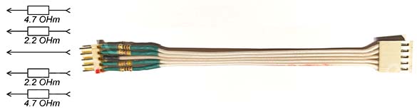 Fig. 10 Voltage equalizer. Scheme and appearance.
If you connect without equalizing the voltage, then if the voltages on the groups of parallel wired cells are very different, the batteries may heat up with their failure, self-ignition, and even explosion. This primarily concerns Li-Ion and Li-Pol elements. After all battery packs are connected, we recommend equalizing the groups of parallel wired cells voltages using an external source. We recommend determining the group of parallel wired cells with the highest voltage and charging the rest to its level. The fact is that the balancer on this BMS controller is quite weak and will balance all the batteries over a large number of charge-discharge cycles, and before that the batteries will not be able to operate at full capacity. If it is assumed that there will be quite a lot of elements in the battery of the charging station, then it is advisable to use a more advanced BMS controller with an active balancer, which will have an effect but will cost a little more.
Troubleshooting and application details
A correctly assembled charging station from preconfigured blocks will already be operational.
One of the most common nuances in work can be described as follows:
- during the charging process it is interrupted, the DV1 voltmeter goes out and the fans stop. The reason is that groups of parallel wired cells of the battery pack are unbalanced and / or the voltage is set too high at the output of the charging converter U2. The BMS controller, therefore, turns off the charging current to avoid overcharging. Troubleshooting should begin by checking the balancing of the groups of parallel wired cells of the battery pack. The voltages on the of the groups of parallel wired cells should not differ from each other by more than 0.02 volts. To reduce the difference in voltages, we recommend recharging the groups of parallel wired cells, where the voltages are lower, with an external power supply. The BMS controller has its own indication - red LEDs light up in those groups of parallel wired cells where the voltage is higher, thus indicating voltage suppression. Actually, this is passive balancing. For more efficient balancing, there are BMS controllers with active balancing that do not use resistors to dampen voltage, but pump energy from the groups of parallel wired cells where the voltage is high to where it is lower. An example of such a BMS controller for 4S LiFePO4 batteries is DL4S-40A. If the groups of parallel wired cells are balanced, but the BMS controller still interrupts charging, the controller may not match the battery type, see fig. 8. If it is, you should check the output voltage of the charging converter U2 in an unloaded state, if it is approximately the same, then there may be less voltage drop across diode D1 than expected. In this case, it is worth reducing the voltage at the output of the charging converter U2 in an unloaded state by about 0.1 volts. If the response of the BMS controller has not changed, you should further reduce the voltage at the output. U2 by 0.1 volt and so on until the BMS controller stops turning off the battery at the end of the charge.
- the laptop is connected and working, but its battery is not charging.
A possible reason is that the laptop manufacturer uses chipping of the network adapter. Only a chipped adapter will be able to charge the battery of such a laptop. Manufacturers saw chipping adapters - Dell, Sony. A possible solution is to buy a faulty adapter for your laptop on the radio market and install the chip in the charging station. In this case, the output to the laptop will be 3-wire.
- The USB adapter is set to 5 volts 20 amperes, and charging the smartphone takes much longer than 20 minutes.
The reason is similar to the previous one, “fast” chargers also “negotiate” with consumers about the “speed” of charging. Due to the insignificance of the problem, no solution was sought.
- while charging the battery (only the internal battery is charged by the built-in charger), the voltage voltmeter on the battery is automatically turned on only in the position of the switch to the internal battery.
This is an operating feature that allows you to simultaneously charge the internal battery, and operate the output converters U4-U6 from an external one. Then the voltmeter will show the voltage of the external battery, i.e. the one from which the output converters operate. There is a variant of the circuit where, if the voltage of the external battery is below the minimum, and the battery switch is in the “external” position, then the red LED lights up, signaling the unsuitability of the battery and the main voltmeter, if charging is in progress, shows the voltage on the internal battery. This complicated the circuit and design and is therefore not included in this article.
Ways to reduce the cost and simplify the design
To reduce the cost of the design, instead of the 24V network stabilized power supply WX-DC2412, you can use another one with a 24V 3-5A output, or even use an unstabilized power source, which is a network transformer with a primary winding of 220 Volts and a secondary winding of 17 - 22 volts, with a rectifier and a smoothing capacitor of at least 2000uF x 50V (better 5000 - 10000uF), look fig. 11. In any case, the charge mode will be observed on the U2 converter.
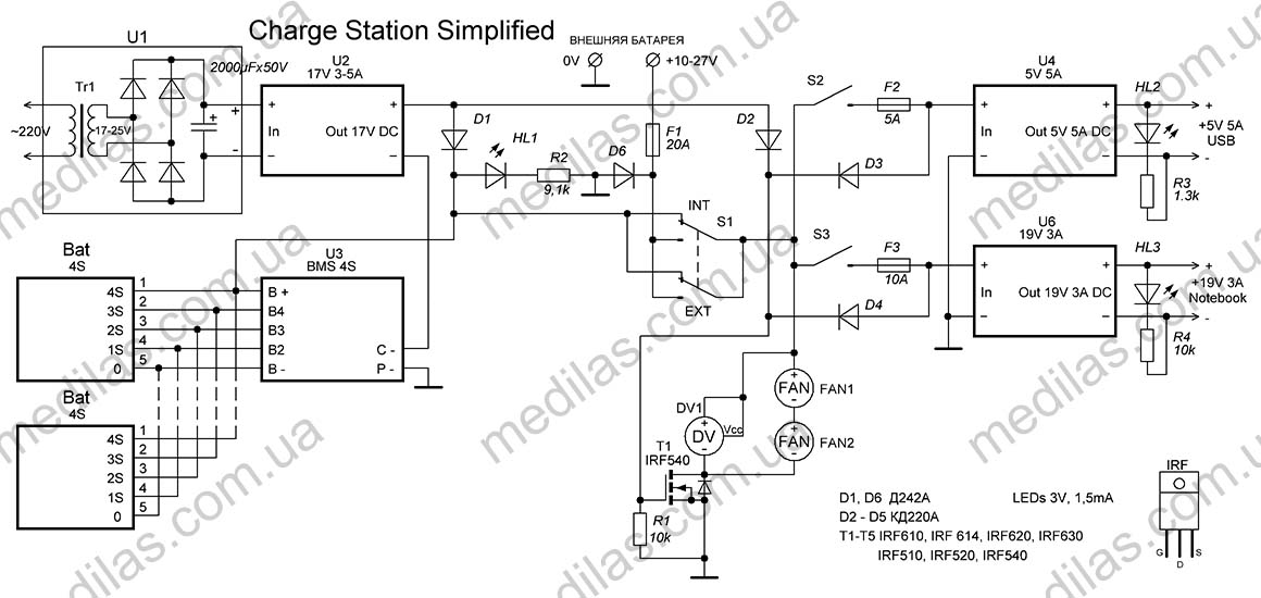 Fig. 11 Circuit of a simplified charging station without additional voltmeters and with a power transformer in U1
You can also exclude voltmeters DV2-DV5 (with field switches T2-T5) from the circuit, especially if the cells for the battery are new or selected for the same group of parallel wired cells capacity. In any case, the BMS controller will try to balance the groups of parallel wired cells and if the imbalance is serious, it will turn off the charging or load.
The proposed BMS controller is quite simple, but at the same time it has its balancing indication, which you can also focus on.
Ways to improve and retrofit the structure
It should be understood that the author first wanted to share the principles of construction and experience in creating charging stations, and then only a description of the finished design.
For example, according to this principle, an office charging station was created with only an external battery on 2 12-volt LiFePO4 (lithium-iron-phosphate) batteries 100 A/h, a total of 24 volts, with an inverter power supply of 4800 W, up to 4 laptops, USB x 5, LED lighting strip 12 volt 5 ampere, JPON - 12 volt modem and 9 volt router. It did not have a BMS controller, since it is built into the batteries, there was only 1 voltmeter showing the total voltage, by which you can navigate the battery charge level. Both charging converters U1 and U2 together served as one modified industrial power supply S-720-36 at 36 volts 20 amperes, whose output voltage was reduced to 33.5 volts by adjustment and the charge also went through a double Schottky diode D1, The current limit was reduced to 15 amperes. To power laptops, 2 converters of 800 watts each were used, etc., but the original principle remained the same.
Also, if you use a lead-based electrochemical system (lead-acid, gel, or AGM batteries), it is critical to prevent them from being over-discharged to maintain their performance. To do this, such a system can be retrofitted with an alarm and/or a voltage cut-off in case of a drop to a certain level.
In general, the versatility of the platform allows you to build systems limited only by the finances and imagination of the master.