

")
")
We set out to find out as objectively as possible what a device for measuring equivalent series resistance should be, so that it would be most convenient and efficient for electronics repair specialists to use.
Measuring the equivalent series resistance of electrolytic capacitors is very specific, in many ways unlike other types of measurements organized in multimeters, because it is necessary to measure small resistances at a relatively high frequency, without desoldering from the circuit. Therefore, even sophisticated multimeters that are capable of measuring capacitance and inductance do not measure the ESR of electrolytic capacitors.
In order to choose the best format or type of device for measuring ESR from the point of view of the repairman, let's compare 3 main options:
- Hand probe - indicator with LED indication.
- Device with pointer indication.
- Instrument with digital display.
Based on the experience of using similar devices, we will analyze some comparison criteria and their significance for measuring the equivalent series resistance (ESR) of electrolytic capacitors.
Accuracy. From my experience with electrolytic capacitors, it is clear that ESR-induced faults will appear if the ESR increases by more than 5-10 times. For example, over 3 years of operation of professional server equipment, the ESR of electrolytic capacitors of one of the power supplies has increased by an average of 5 times, but at the same time everything continues to work without failures. It is also noted that the heating of some electrolytes to 30 - 40 OC lowers ESR by about 1.5 times. Then, after cooling down, the ESR is restored. Thus, for the purposes of diagnostics and repair, an error of 20 - 30% is acceptable.
Probe design. This interesting aspect is related to the fact that it is necessary to measure low resistance values, also at high frequency. Try measuring the 0.1 ohm resistance across the digital multimeter leads, especially when the lead wires are a little frayed and the reading varies with lead position. All this is further aggravated when measuring at a high frequency. The high accuracy of the instrument will be minimized by the simple use of wire probes. From this point of view, it is necessary to minimize the length of the conductors from the device to the tested electrolytic capacitor. There is an option to compensate for resistance using 4-wire probes, but this will complicate their design. The option of using the terminals on the switch or digital is ideal only for soldered capacitors.
Speed reading, convenience. There are two aspects here:
- The maximum proximity of the indicator to the measurement site. The effect is the same as the mirrors for the driver.
- The rate of level estimation from the turnouts and from the bar graph display is much faster than from the digital ones. Therefore, some digital instruments are equipped with an additional level indicator in the form of strips on the display (see Fig. 1).
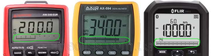
Fig.1 Graphic level indicator (bar graph) in multimeters
This in particular allows you to better track rapid level changes. A person has the highest reaction speed to sound indicators, which is also used in digital multimeters in continuity modes, but I believe that indicating ESR, say, with a tone of sound vibrations, is too much.
Hand probe - LED indicator
Pros:
- There are no probe wires, (the specifics of measuring the ESR of electrolytic capacitors is such that the slightest wear of the wires already significantly affects the measurement accuracy).
- Of all instrument options, the most compact and small-sized.
- The ability to check capacitors in boards and installations without taking your eyes off the probe connection points, because small dimensions and LED indication contribute to this. Therefore, the highest convenience and speed of electrolyte testing.
- No need for a microcontroller. Resistant to falling, shock.
Disadvantages:
- Slightly more complex than the pointer due to the need to use a specialized LED indication chip.
- Lower accuracy than the other two due to the limited number of indication LEDs.
Switch instrument
Pros:
- Easiest of all.
- No microcontroller needed.
Weaknesses:
- The large (compared to LED) dimensions of the pointer device do not allow it to be made manual, and this is the need for wire probes to check electrolytic capacitors in circuits.
- Due to the use of a switchman, fragility, sensitivity to falling.
- Lower convenience, you have to shift your eyes to the arrow, then to the probes.
Digital device
Pros:
- Highest precision. High accuracy, if this leads to a complication of the circuit, is justified only for monitoring manufactured capacitors on a factory assembly line.
- It is easier to organize the simultaneous measurement of the capacitance of the capacitor - for repair it is necessary much less often than the measurement of the equivalent series resistance, and also leads to the complication of the circuit.
- Resistant to falling, shock.
Disadvantages:
- The need to use wire probes to test electrolytic capacitors without soldering from the circuit.
- Lowest convenience - digital readings take longer to read than LED and pointer readings.
- The most difficult option to repeat, the need for a microcontroller, a digital display.
Conclusions: Based on the above, for the vast majority of work, both on the road and in the workshop, an adequate manual probe is convenient - an indicator on LEDs.
As they say: Everyone should have this! One digital device is enough for a workshop (a group of craftsmen) to analyze special cases.
And switchmen, due to the simplicity of their circuit and design, are good for repetition by novice amateurs.
More characteristics that a device for measuring the ESR of oxide electrolytic capacitors should have:
- The ability and ability to take measurements without removing the capacitor from the circuit. In this case, the circuit must not be damaged by the device and the circuit circuits must influence the measurement result as little as possible. To do this, the voltage on the open probes must be less than the firing limit of n-p transitions of semiconductor components, including Schottky transitions, i.e. no more than 200 mV.
- To be portable, rechargeable, with a continuous operation time of at least 4 hours.
- Small dimensions and weight.
- To be able to withstand voltages accidentally applied to the probes, preferably up to 300-350 V (voltage on the electrolytic capacitor after rectifying the network is 220 V).
- Measurement frequency 30 - 100 kHz (operating frequencies of most switching power supplies).
- The range of capacities of tested electrolytic capacitors is from 1 uF to infinity.
October 14, 2014, Odessa, UKRAINE