

")
")
A practical design of an inexpensive and efficient Power Bank is presented for quick self-assembly, providing uninterrupted Internet access
The task was to assemble a simple power system for a GPON modem and a Wi-Fi router with charging from the mains, as autonomous as possible, corresponding to the “plug and forget” principle, at minimal cost, quickly, and adaptable to any type of the rechargeable battery. Other conditions were maximum efficiency when powered by batteries and availability of parts.
To simplify and speed up assembly, it was decided to assemble a powerbank using commercially available ready-made modules.
Principles of constructing uninterruptible power supplies
The principle of on-line construction was chosen, when consumers are powered through converters from batteries, the batteries are charged and the voltage on them is maintained according to the presence of voltage in the mains. It is this construction topology that has maximum efficiency when powered by a battery and satisfies the “plug and forget” operating principle. Another important advantage is the ability to build and easily adapt to any type of battery. For example, one of the options was built and worked perfectly on a gel battery with one closed can! This “unpretentiousness” to batteries allows you to use (after selection) even those that are left in workshops for repacking batteries, and really, in each such service center, every working day there are 10-30 cells that have lost their capacity but are still suitable.
Another topology based on a purchased UPS (Uninterruptible Power Supply) is MUCH less economical and costs more, although it is easier to implement. In other words, a battery from the same UPS, but connected to an on-line circuit, can last the same consumers tens of times longer than when working in its own UPS. This is explained by the fact that converting from 12 Volts to 220 AC, and then back to 12 and 9 Volts is MUCH less economical than converting similar DC voltages.
Another option for constructing an uninterruptible power supply circuit is to use a USB powerbank with boost converters attached to it to power the modem and router. In terms of efficiency, this is much better than the option of using a UPS, but it has its own suboptimalities. In addition, a USB power bank is sometimes needed to solve other issues.
Description of design
Powerbank schematic diagram
The design of the specific powerbank described is based on the following:
- On-line topology, “plug and forget” principle
- Power supply for Wi-Fi router - 9V, 200mA
- GPON modem power supply - 12V, 200mA
- The presence of a large number of battery cells GP 380AFH, asking for recycling.
I read somewhere on the forums that TP-Link routers with a 9V power supply can also be powered with 12V, but I didn’t want to check, risking burning the router. Based on this, and also to ensure maximum efficiency when powered by batteries, it was decided to use 2 ready-made pulse stabilizing converters.
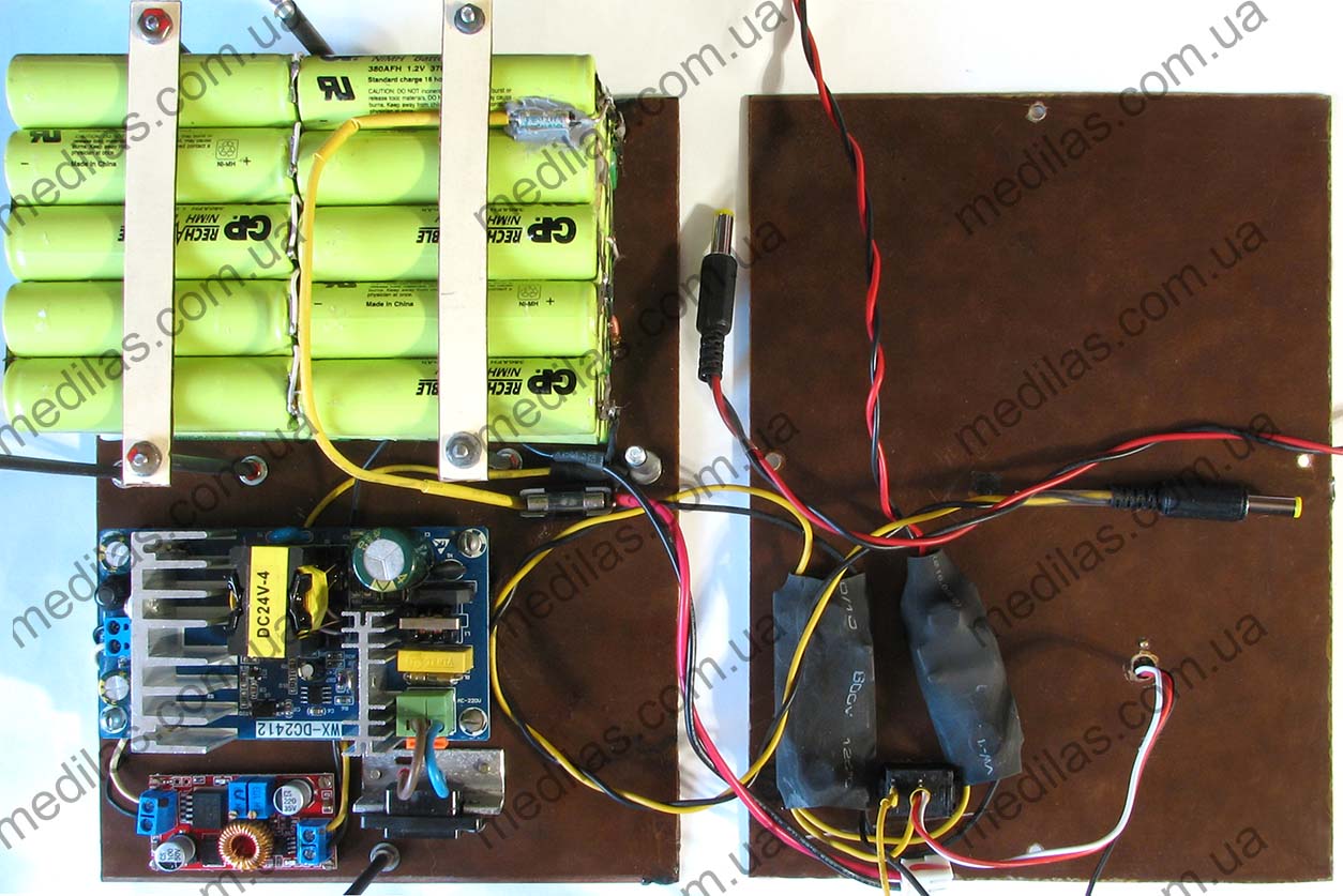
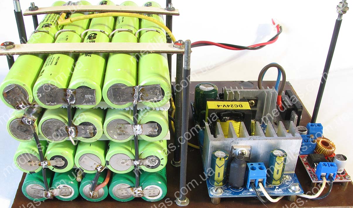
Powerbank inner view and component placement
Prices for components for November 2022:
- Unpackaged power supply for 220V AC 24V DC WX-DC2412 9.25 US$.
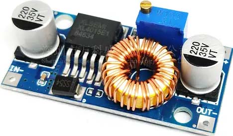
- Buck converter with voltage and current regulation for XL4015E1 (for charging circuit) 2.75 US$.
- Buck converter with voltage regulation on XL4005 (for 9V output) 1.7 US$.
- Boost-buck converter for XL6019 (for 12V output) 3.5 US$.
- Digital voltmeter 2.7 US$
- Post services about 3.75 US$.
- Total 23.65 US$.
All parts are readily available and can be purchased at your local radio market or online.
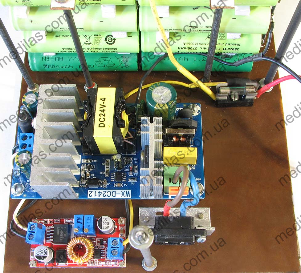
Electronic modules placement
The batteries were collected from a tank for used batteries, which were not handed over to the collection point due to lack of time. This is how useful it can be to collect used batteries for recycling). Of about 150 NiMH GP 380AFH elements, the best 50 were selected based on capacity and assembled into blocks of 10 pieces for 12 volts. The selection was made using Opus BT-C3100 and SkyRC MC3000 chargers, powered directly from a 12-volt battery to ensure uninterrupted operation. Opus BT-C3100 turned out to be more effective for selecting these specific elements than SkyRC MC3000, although the first is considered household, and the second is professional.
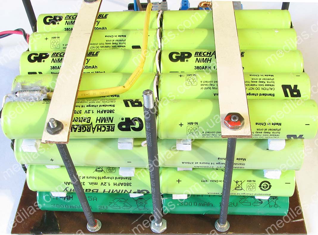
Powerbank rechargeable batteries pack made of NiMH GP 380AFH x 50
A 10A 85-degree thermal fuse is installed inside each block. (not shown in the diagram). Blocks of 10 pieces were mechanically fastened to each other using transparent silicone and Moment-Crystal glue with a gap of 4-5 mm between them for cooling. Despite the selection of elements, a significant scatter of characteristics was observed both in capacity and internal resistance. Therefore, it was decided to connect all the corresponding elements of each block in parallel. This idea arose at the selection stage, so elements were selected into blocks so that an element with a lower capacity would be parallel to an element with a larger capacity. Since the charge-discharge currents are small, it was decided to neglect the selection based on internal resistance.
Powerbank side view
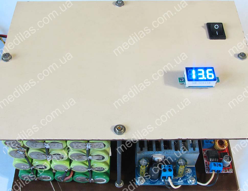
Powerbank appearance
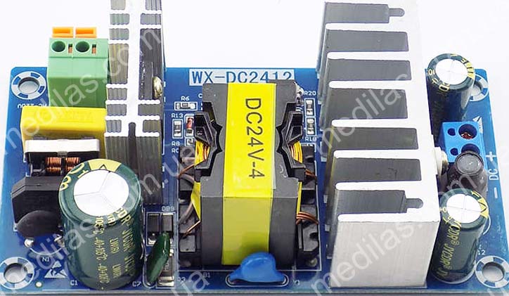
U1 Power supply unit WX-DC2412 220V AC to 24V DC 4A max
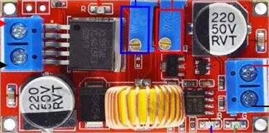
U2 Step down converter used as the battery charger. It lets adjust the output voltage and maximal current. The potentiometer in red sets the current, in blue, and accordingly adjusts the output voltage.
U3 Cheap step down converter with output voltage adjustment
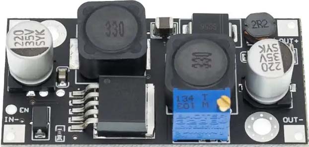
U4 Step up-down converter with output voltage adjustment
The output voltage of the converter U2 was set to 14.1 volts, the maximum current is 1.5A, which corresponds to a battery charging current of about 1.1A.
Plastic panels, studs, nuts, etc. from garage scrap. The wires are from old computer power supplies, a diode, a switch, plugs, and connectors from disassembly, but if they are not there, then they are mere trifles in radio stores.
The plugs to the router and modem are the same 5.5x1.5 with a plus in the middle and a minus on the outside.
Practice has shown that a full battery charge is enough for more than 24 hours of continuous operation.
This is a description of the NiMH battery design using GP 380AFH cells.
Another design was assembled using LiFePO4 elements.
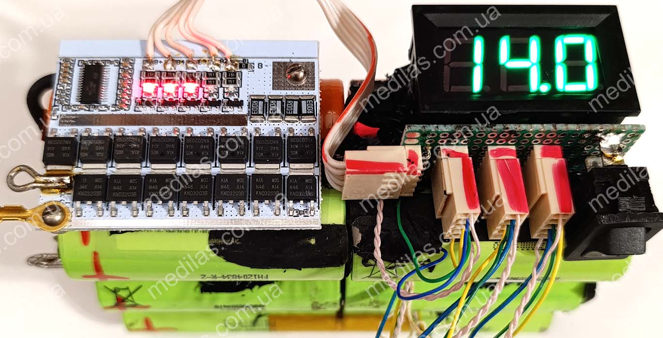
Powerbank made of 3 x 4S LiFePO4
If longer battery life is required, you can connect additional 12V batteries in parallel with the main one or select a battery with a larger capacity. You can even connect a car battery (the current of the step-down charging converter can be increased to 3A and more), or you can use a “dead” battery that no longer cranks the starter. An acquaintance made a powerbank using this “recipe” and connected it to a car battery that had served for about 5 years, with 1 cell shorted, and says it is enough for about 15 hours of continuous operation.
Battery selection
The battery can be installed gel or AGM, same as for uninterruptible power supplies, 12V, 7-9-12 A/h. You can also use a classic lead acid, gel, or AGM battery with a sprinkled (shorted) 1 cell. And, of course, you can use 4S (4 series-connected elements) LiFePO4 and Li-Ion - Li-Pol batteries from selected elements, but in this case, the selection is stricter and the use of a BMS (battery management system) (balancer, balancing board) is mandatory. Li-Ion - Li-Pol batteries can be obtained from workshops that repack batteries for laptops and power tools. If several batteries are used, they must all be powered by the same electrochemical system. If, say, a lead battery with a shorted cell is used, then in parallel to it for amplification, you can connect the same lead battery with a shorted cell. You can even use 6 Volt batteries, but in this case, the converters U3 and U4 must be boost converters. In one article it is difficult to describe all possible options for using batteries in such an uninterruptible power supply. In all cases, it is necessary to adjust the voltage of the charging unit (converter U2).
Approximate output voltages of converter U2
| Battery | Converter U2 output voltage | |
|---|---|---|
| D1 non Schottky | D1 Schottky | |
| Lead, gel or AGM, 12V all cells work | 14,2 - 14,4 | 13,9 - 14,1 |
| Lead, gel or AGM, 12V 1 cell shorted | 12,0 - 12,2 | 11,7 - 11,9 |
| NiMH, NiCd 10S | 14,2 - 14,4 | 13,9 - 14,1 |
| LiFePO4 4S | 14,4 - 14,6 | 14,1 - 14,3 |
| Li-Ion, Li-Pol 4S | 17,0 - 17,5 | 16,6 - 17,1 |
| Li-Ion, Li-Pol 3S | 12,9 - 13,3 | 12,5 - 12,9 |
* the number before S means the number of elements connected in series.
If a Schottky diode is used as D1, the voltage at the output of the converter must be reduced by approximately 0.4 V. To avoid excesses with batteries and load (modem + router), all converters must be configured before being included in the power bank. Confusing + and - is strictly prohibited.
Setting the limiting current of the charge converter U2 corresponds to the principle that the larger the battery capacity, the higher the current the charge converter U2 can be set to. Battery charging current = limiting current of the converter U2 minus current consumption of the load (modem + router) through the converters. It is not advisable to reduce the charge current below 0.1C and should not be higher than 1C, where C is the battery capacity. The higher the charge current, the faster the batteries charge and the faster they lose capacity during operation. If the charging current is too low, there is a risk that the battery will not have time to charge during the short time of electricity availability. There is an opinion that some average optimal charging current for lead, gel and AGM is 0.2C, for example, for a 12V 7A/h battery the optimal charging current will be 1.4A, and for other types of batteries 0.3C.
It should be remembered that car unsealed lead-acid batteries emit harmful gases during operation, so it is better to place them in ventilated areas. To significantly reduce the emission of gases, as well as to extend the service life of such a battery, it should be operated in the temperature range of 10-25oС, charged with a current of no more than 0.1 C to a voltage of no more than 14.3 V and discharged no deeper than 10-11V.
You should also follow the operating rules for the corresponding batteries, the main ones of which are: do not heat above 60oС, do not allow polarity reversal, short circuit, overcharge, and overdischarge.
Diode D1 (in the described design a Schottky diode SB340 is used) is needed to ensure that the batteries are not discharged through the charging converter U2 and the power supply. If it is excluded, then during a loss of 220V mains voltage, the battery will be additionally discharged through the charging circuits with a current of about 30 mA. This will reduce its uptime by 7-8%. It is better to choose a Schottky diode as a diode; it has a lower forward voltage drop, with a maximum voltage of at least 30 V and a maximum current of 3-6A (preferably more). Diodes recommended for use as D1: Schottky: 1N5844, SB340, SB350, SB540, SB550, 1N5822 Non Schottky: FR601 - FR607, FR501 - FR507
Ajustment
The adjustment is simple and consists of the following:
- Adjustment of modules U2, U3, and U4 is carried out before installation in the power bank circuit.
- The voltage at the output of the step-down charging converter U2 depends on the battery used and is approximately set following the table given above. The output current limitation of the step-down charging converter U2 depends on the capacity of the battery used and is described here.
- Converters U3 and U4 are adjusted to the voltages required by specific consumers (modem and router).
This completes the adjustment.
Assembling
Assembling is carried out after adjusting modules U2, U3, and U4. The assembled power bank should be carefully checked for polarity reversals and short circuits, and only then connected to the battery and plugged into the network. It should be remembered that electronics do not forgive polarity reversals.
This type of powerbank can also be used for video surveillance systems, to power home routers and modems, and ethernet provider switches to ensure uninterrupted wired Internet. In this case, you can simplify the design by eliminating one of the buck converters.
Ways to reduce the cost, simplify and modernize the design
To reduce the cost of the design, you can use a linear voltage regulator LM7809 instead of the U4 step-down converter. This solution will slightly reduce the efficiency when powered by batteries. If 4S Li-ion or Li-pol is used as a battery, then instead of U3 it is advisable to use not a step-up or step-down converter, but a cheaper step-down converter or even a linear voltage regulator LM7812. Instead of the 24V network stabilized power supply WX-DC2412, you can use another one with a 24V 3-4A output, or even use an unstabilized power supply, which is a network transformer with a primary winding of 220 Volts and a secondary winding of 15 - 20 Volts, with a rectifier and a smoothing capacitor not less than 1000uF x 50V. In this case, stabilization will be on the U2 converter. If a lead, gel, AGM, or NiMH, NiCd battery is used (without a BMS controller), it makes sense to assemble a load cut-off device based on the minimum specified voltage on the batteries. This can significantly extend the life of the batteries.
It was also noticed that the recommended charging converter U2, with a set charge current of more than 1 A, gets quite hot (but still works). The reason is its choke. If a charging current of more than 1 A is required, it is desirable, and when setting a charging current of more than 2 A, it is necessary to either select another, more powerful converter with current and voltage regulation or modify this one by rewinding the inductor with a slightly thicker wire and increasing the number of turns by 20%. You can also install a common-mode choke taken from disassembling an ATX computer unit instead of the original choke.
The design described above provides great opportunities for modernization, both in terms of increasing the battery capacity and adding new functions. For example, you can turn a power bank into a charging station by making outputs for USB and/or for a laptop or other gadget you use.
To organize USB charging, you need a step-down converter set to 5 volts 3 amperes.
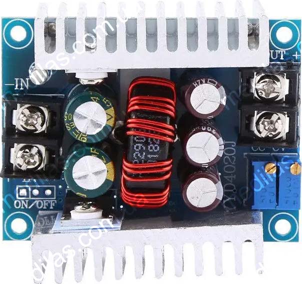 Step down DC-DC converter in LM25116, Uin-6~40V, Uout-1.2~36V, 20A, with voltage and current adjustment
It should be connected to the battery through a fuse and a switch. You can connect 2 USB sockets to its output, which can easily be found on the radio market or in online stores. We install sockets from disassembled old motherboards. Another LED (via a resistor) can be connected to the output of the converter to indicate the presence of voltage at the USB output.
The same converter (configured accordingly as described above) is recommended to be used as charger U2 if the battery capacity exceeds 10 A/h.
Using the same principle, you can make an output for powering a laptop (usually 19 or 21 volts), for this you will need a boost converter configured for the appropriate output voltage and current of 5-10 amperes.
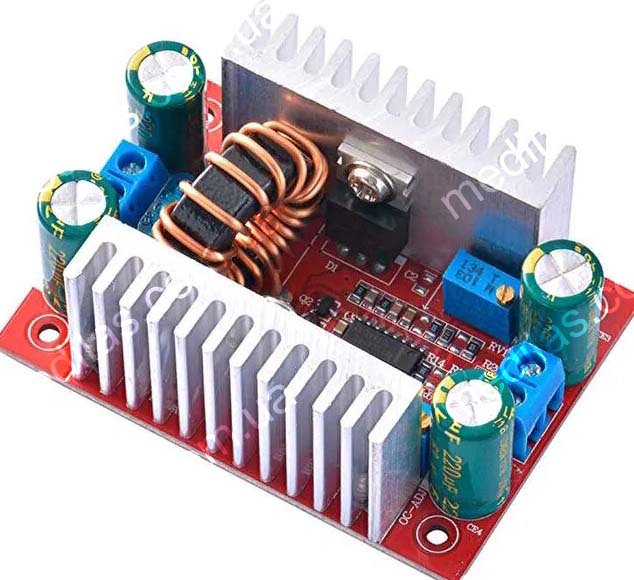 Step up DC-DC converter in TL494, Uin-8.5~50V, Uout-10~60V, 400W, with voltage and current adjustment
It should also be connected to the circuit via a fuse and a switch. We recommend making the output using a pair of female-male XT30 connectors, joining the male connector to a purchased cable with a laptop power connector. Such a cable can also be found on the radio market or in online stores.
Another idea is to equip the power bank with a lighting LED or strip in the same way.
Therefore, we recommend that if you plan to work with high-capacity batteries, leave some space for additional converters and your fantasy.
Instead of a conclusion
With this article, the author wanted to share not so much the finished design as the principles and ideas underlying it.
You should also understand that uninterrupted Internet will be guaranteed if you use GPON (Gigabit Passive Optical Network) (fiber optic) data transmission technology. This technology directly connects the provider and the user and does not require intermediate routers and switches. In the case of using a wired communication channel over twisted pair, intermediate routers, and switches are required, which also require an uninterrupted power supply. Typically, providers do not bother to ensure uninterrupted power supply to equipment located outside their premises. This leads to the fact that if there is no power supply along the signal path between the provider and you, even if the power supply to your router is uninterrupted, there will be no Internet access. After all, along the path of a signal traveling over a twisted pair cable, there will be dozens of switches, hubs, and routers that also require power. In other words, if you have wired Internet, then to ensure uninterrupted access you need to switch to GPON (fiber optic). To do this, it is usually enough to leave a request with your provider.