

")
")
The practical design of a simple and effective charging station, easily and quickly assembled at home from inexpensive, common parts, is described
The task was to quickly assemble a simple and inexpensive charging station with automatic recharging from the mains, at minimal cost, quickly and adaptable to any type of battery. The condition was to create the most universal platform, subject to various retrofits and operated according to the principle “plug the cord into the socket and don’t worry about keeping the accumulator charged.” Also, a condition was maximum efficiency when powered by batteries. In other words, it was necessary to obtain the maximum effect for a minimum of money and time.
To simplify and speed up assembly, it was decided to assemble the charging station using commercially available ready-made modules and garage trash.
The circuit and design of the specified charging station described is designed and executed based on the following conditions:
- The presence of a large number of Li-Ion 18650 battery cells asking for recycling
- Possibility of operation from both internal and external batteries
- External battery input voltage range 9-18 volts (omnivorous)
- Automatic charging from 220 volt mains, charging only the internal accumulator
- USB output 5 volts, 3-5 A
- Output to laptop 19 volts 3 A
- Adjustable output to a soldering iron (for power adjustment) 150 - 260 volts DC 0.3 A (optional)
- Since there is an external battery 12 volt 100 A/h and an inverter, the formation of ~ 220 volt charging station is not required
Availability of a sufficient amount of garage scrap (getinaks panels, hardware, old domestic radio components, wires, corners, etc.) To speed up assembly and reduce the cost of design - maximum use of garage trash and disassembly (wires, studs, nuts, textolite, diodes, transistors, connectors, etc.)
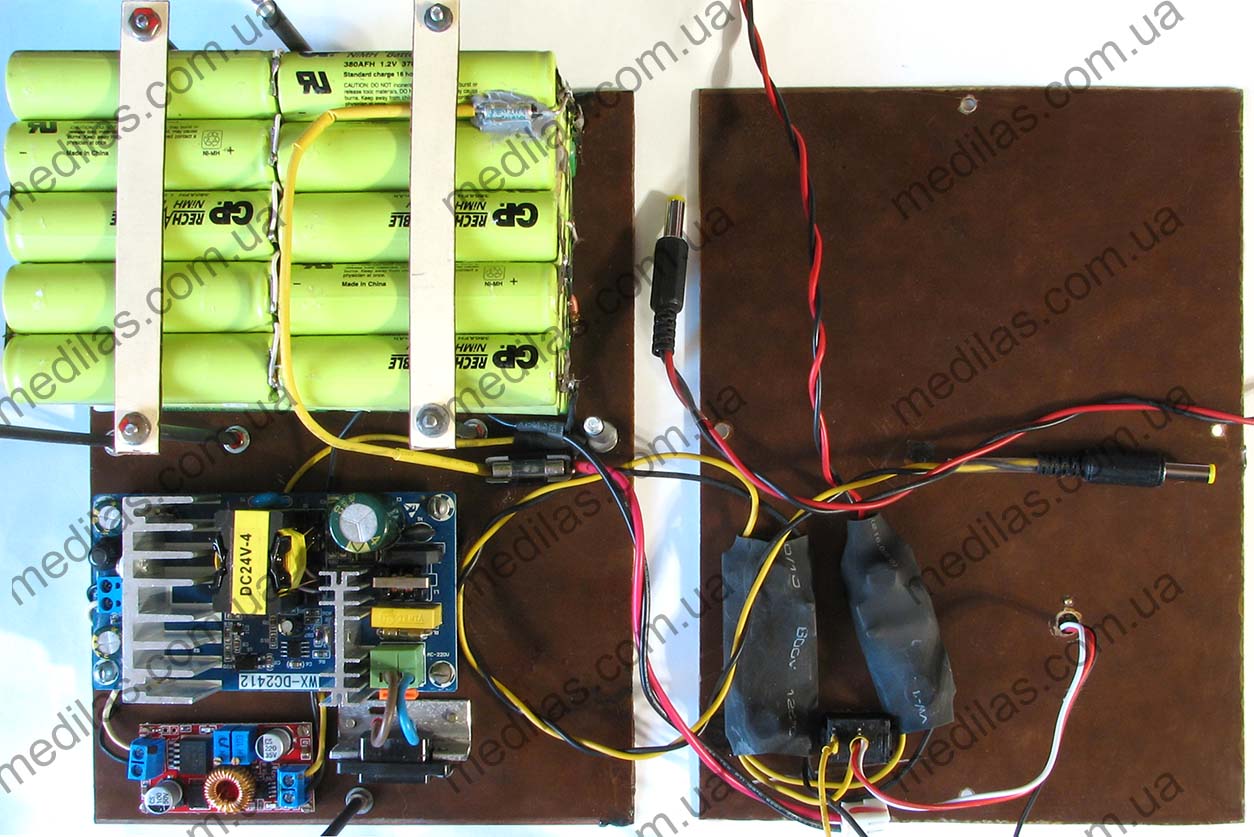
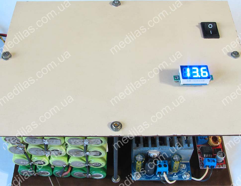
The appearance of the charging station without the top cover is shown in fig. 1.
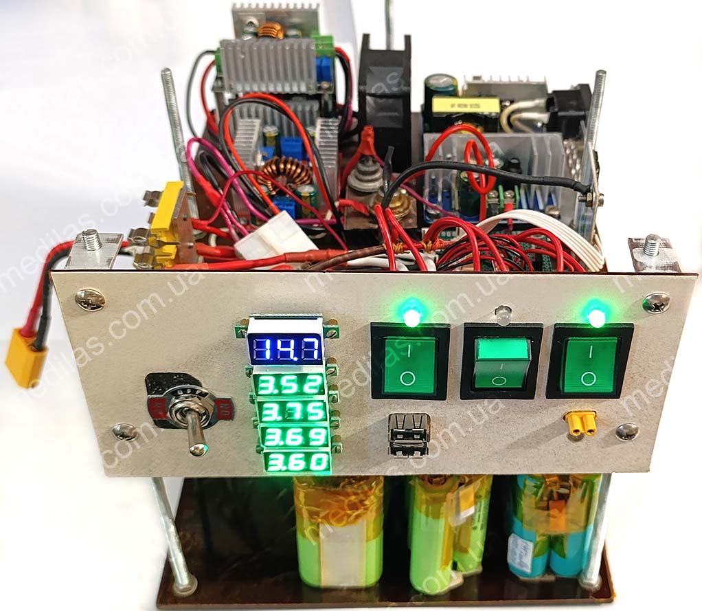 Fig. 1 Charge station
Of course, the needs in each case may be different, for example, power for a soldering iron is not required, but power for 3-5 laptops is needed with a voltage of not 19 volts, but 21 volts. Therefore, it is more important to be guided by ideas and implementation principles, rather than copy a specific design. But, to speed up the repetition of the design, if somebody asks us, we will also include the drawings. The design was based on the principle of powering devices with their specific voltages, rather than converting them to 220 volts, which corresponds to the principle of the highest efficiency when powered by batteries. This efficiency results in much longer battery life. Another topology based on a purchased UPS (Uninterruptible Power Supply) is MUCH less economical and costs more, although it is easier to implement.
Description of the electrical circuit diagram of the charging station
Description of the electrical circuit and operating principle of the charging station
The on-line principle was chosen, when consumers are powered through converters from batteries, and the batteries are charged and the voltage on them is maintained according to the presence of voltage in the mains. It is this construction topology that has maximum efficiency when powered by a accumulator and satisfies the “plug and forget” operating principle. This design principle allows us to consider such a system as a flexible and universal platform for building an energy supply system for home and office. Another important advantage is the ability to build and easily adapt to any type of battery. For example, one of the options was built and worked perfectly on a gel battery with one closed can! This “unpretentiousness” to batteries allows you to use (after selection) even those that are left in workshops for repacking battery packs, and, believe me, in each such service center, every working day there are 10-100 cells that have lost their capacity, but are still suitable. Such elements can be found in workshops for repacking electric vehicle batteries (electric cars and scooters, hoverboards, etc.), repairing laptops and cordless power tools (screwdrivers, etc.). Such elements and batteries are sold cheaply even on the radio market. In other words, a battery from the same UPS, but connected to an on-line circuit, can power the same consumers much longer than when working in its own UPS. This is explained by the fact that converting from 12 volts to 220 AC, and then back to 5, 12 and 19 volts is MUCH less economical than converting similar DC voltages.
The charging station diagram is shown in fig. 2.
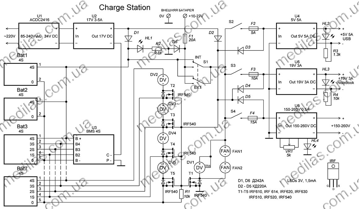 Fig. 2 Charge station schematic diagram
The battery packs are charged by a DC power supply U1, which has a 24 volt output of 3-6 amperes of stabilized or unstabilized voltage. To speed up assembly, you can use a ready-made purchased power source, and to reduce the cost, you can get by with a transformer with a diode bridge and a smoothing capacitor (see Fig. 11 Diagram of a simplified charging station). The charging mode is formed by a step-down converter U2, on which it is necessary to adjust the final charge voltage and current before starting the operation.
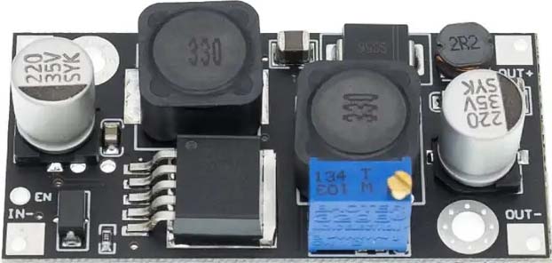
The step-down converter used as U2 is shown на fig. 3
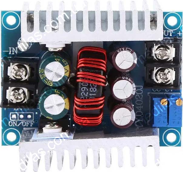 Fig. 3 Step down DC-DC converter in LM25116, Uin-6~40V, Uout-1.2~36V, 20A, with voltage and current adjustment
This two-stage circuit provides modularity and does not demand the stability of the output voltage of U1 unit. It is assumed that the charging circuit is constantly connected to the mains (even a switch is not provided) and recharges the batteries as needed. The accumulator charging circuit also includes a diode D1, which is designed to eliminate battery discharge through the U2 converter when there is no mains power.
Toggle switch S1 is designed to switch the external and internal batteries and must be designed for sufficient current.
Diode D6 together with fuse F1 forms system protection against polarity reversal.
Voltmeters DV2-DV5 are designed for more careful monitoring of voltages in battery pack sections. Voltmeter DV1, let's call it "main", shows the voltage that is supplied to the consumer converters. To ensure that the voltmeters are turned on only during operation or charging, a circuit consisting of T1 - T5, R1, D2 - D5 is provided. The circuit works as follows: When the system is disconnected from the mains and no consumer converter is turned on, the field-effect transistors are closed because there is zero voltage at their gates, thanks to R1. If switches S2 - S5 turn on at least 1 consumer, or a charging voltage appears at the output of the converter U2, then the transistor-opening voltage is supplied through the corresponding diode D2-D5 and the voltmeters are turned on.
In addition to the voltmeter DV1, transistor T1 also includes 2 12-volt fans FAN1 and FAN2, connected in series. This inclusion will reduce the noise level and current consumption of the fans and makes it possible to do without a voltage stabilizer supplied to them.
Consumer converters are switched on via fuses F2 - F4 by switches S2 - S5. The number and configuration of converters correspond to the requirements for a specific charging station, for example, most users do not need a soldering iron converter, but sometimes it is necessary to connect a 12 volt DC inverter to 220 volt 50 hertz. Such a charging station was made with 3 step-down converters, adjusted to an output of 13.5 volts 10 - 12 amperes, and fed an inverter with a pure sine wave output. Why 13.5 volts and not 12? Both the converters and the inverter with this setting have greater efficiency, and the maximum input voltage of the inverter, according to its instructions, was 14 volts.
Batteries used in this charging station
When working with batteries, you should follow safety precautions. To avoid explosion, fire, chemical poisoning, and other negative consequences, it is strictly forbidden to short-circuit cells and batteries, overheat, overload with current more than permissible, disassemble, or exert destructive mechanical influence. This is especially true for Li-ion and Li-pol cells and batteries.
It was decided to organize the battery cells into battery packs of 12 pieces, 4 in series (4S) and 3 in parallel. Because the selection occurred quite slowly (4 elements that turned out to be suitable were driven in the Opus-3100 for 4 - 6 hours), the selection of elements and recruitment into batteries continued even after the assembly of the charging station. But in general, the dimensions of the 1st floor made it possible to accommodate 7 such battery packs, i.e. 84 cells in total. Considering that the average capacity of the selected elements is about 1700 - 1800 mAh, the energy of such a battery pack will be about 500 Wh.
We had at our disposal 2 4S battery packs made of 12 Li-Ion elements, with their own built-in BMS (Battery Management System) module controller, each tired, but still capable of something, and it was decided to use them as is (in the diagram Bat1 and Bat2). This is also due to the duration of the selection of individual elements. The rest had to be taken apart and each element had to be selected for “professional suitability”.
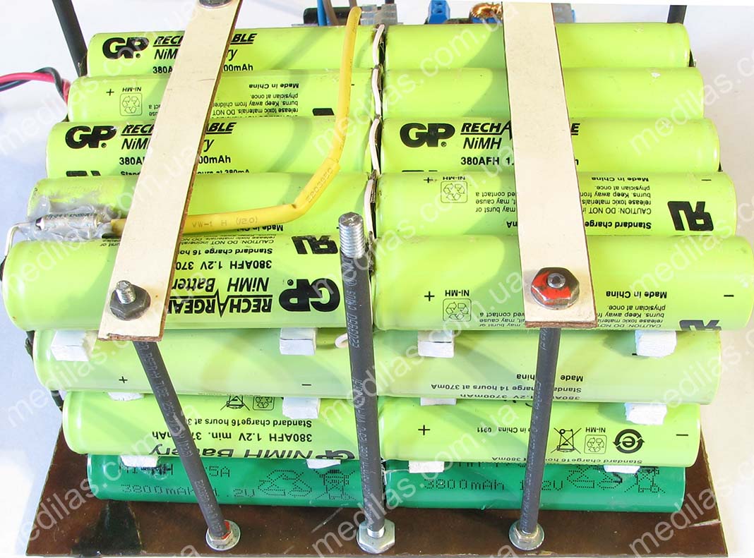
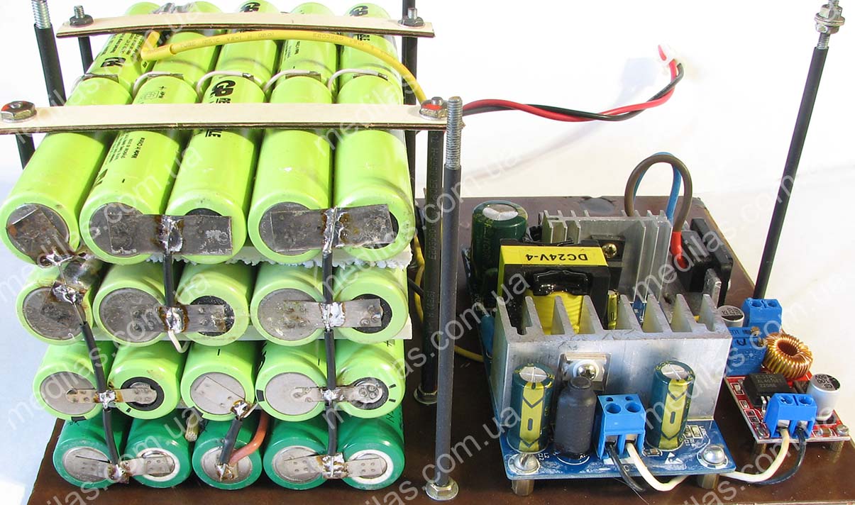
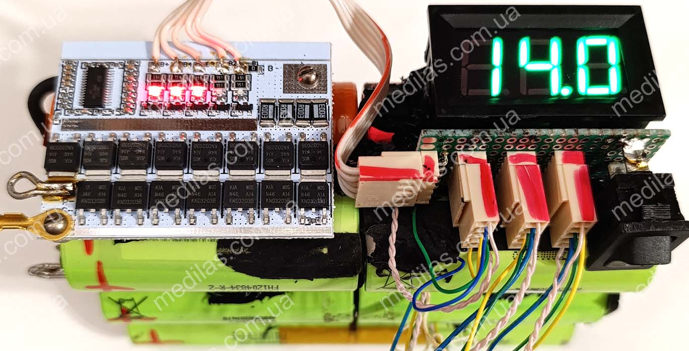
Fig. 4 Battery packs used in the described charging station
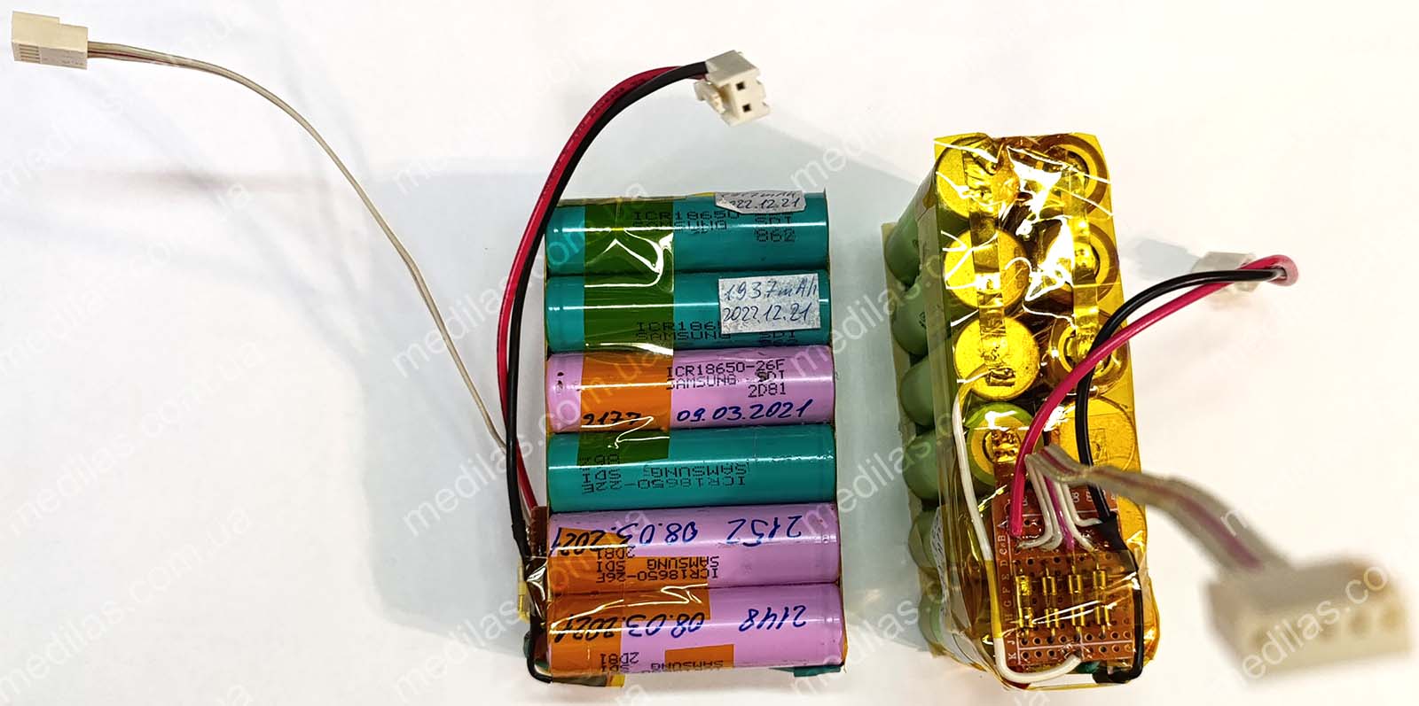 Fig. 4 Rechargeable battery packs used in the charging station
* the number before S means the number of elements connected in series.
The battery packs were connected in parallel, the intermediate connections of the battery packs were also taken out and connected in parallel and finally connected to the BMS (Battery Management System) controller U3, the use of which is mandatory with lithium batteries. Its purpose is to protect the batteries from overcharging and overdischarging, which in turn affects the accumulator life and safety of use. In case of detection of voltage exceeding 4.2 volts (overcharge) on at least one of the 4 groups of parallel wired cells, the BMS controller breaks the battery charging circuit. If the BMS controller detects a voltage drop below 2.7 volts on at least one of the 4 groups of parallel wired cells (over-discharge), the BMS controller will break the battery load circuit. This BMS controller, like most others, if the protection is triggered, breaks the negative pole of the batteries.
A schematic of each repackaged battery pack is shown in fig. 5.
 Fig. 5 Circuit of the rechargeable batteries used in the charging station
Each battery packs has 2 outputs - a power output with 2 contacts, female, and a balancing output with 5 contacts, female.
Rechargeable battery selection
One of the distinctive features of the proposed circuitry is the ability to work with any type of accumulator with a voltage from 9 to 18 volts. At least in this voltage range tests were carried out. So, for example, to check the operation of the charging station from an external battery, we connected a car battery with one shorted can.
But there is one essential condition: if we assemble, say, a battery pack from several batteries, they must be of the same electrochemical system. That is, it is in no way possible to include in parallel, say, a battery pack of Li-ion cells with a battery of lead chemistry, or with a battery on LiFePO4 cells. If an electrochemical system is chosen, e.g. Li-ion or Li-pol, then all cells of all battery packs connected in parallel must be of this electrochemistry. This limitation can be overcome by switching between internal and external batteries because these batteries will not "meet" each other in parallel. For example, in the described charging station the internal battery pack is 4S Li-ion, and as an external accumulator we tried both a lead-acid car battery with 1 closed bank and 6S LiFePO4 (18 volts) and everything worked perfectly.
There is an opinion on the Internet that 6S lead electrochemical batteries (lead-acid, gel, or AGM), 4S LiFePO4, and 10S NiCd and NiMH batteries have approximately the same voltage, about 12 volts, but we still do not recommend connecting them in parallel as there are some differences in their charging and discharging curves.
Another condition is that, as mentioned above, Li-ion, Li-pol, and LiFePO4 cells must be connected via a BMS (battery management system) controller. As already mentioned, Li-ion, Li-pol, and LiFePO4 cells can be "found" in workshops where batteries for notebooks and personal electric transport (electric cars, electric scooters, gyroscooters, etc.) are repacked. These, as well as NiCd (nickel-cadmium) and NiMH (nickel-metal hydride) cells could be found in power tool repair shops. It is essential to check the elements obtained in this way for their "professional suitability", i.e. to select them at least according to their capacity and preferably also according to their internal resistance.
Description of the charging station design
The design of the charging station was chosen to be two floors, with battery packs on the first floor, and all electronics, switching, and indication on the 2nd floor.
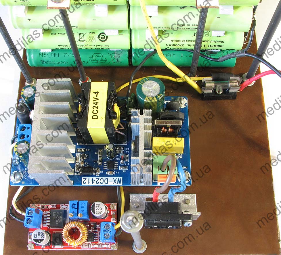
The appearance of the electronics compartment without the top cover is shown in fig. 6
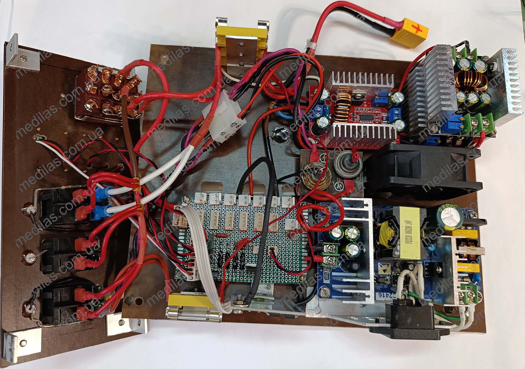 Fig. 6 External view of the electronics compartment of the charging station
The appearance of the front panel is shown in fig. 7
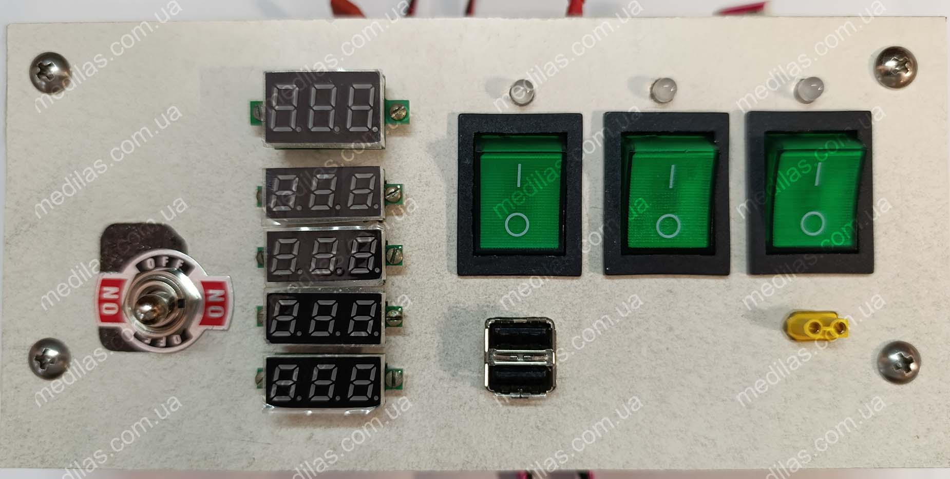 Fig. 7 Front panel appearance
All battery pack terminals are connected on the 2nd floor in parallel on a circuit board, on which a circuit with T1-T5, D2-D5, and R1 is also assembled. The entire design is made using connectors, suggesting modularity. Diodes D1 and D6 are quite powerful, mounted on a separate rectangular piece of getinax. All fuse holders are assembled on brackets at the edges for easy monitoring and replacement of fuses.
The battery elements were collected from tanks for used batteries, which were not handed over to the collection point due to lack of time. Sometimes it is useful to collect used batteries for recycling instead of stupidly throwing them in the trash). Of about 400-450 Li-Ion elements of the 18650 format, the 60 best were selected by capacity and assembled into 5 blocks of 12 pieces at 14.8 volts. Another 2 battery packs were in relatively working condition and had their own built-in BMS controllers. The selection was carried out by a charging and testing device Opus BT-C3100, powered directly from a 12-volt battery to ensure uninterrupted operation. A 10A 85-degree thermal fuse is installed inside each block. (not shown in the general diagram). Despite the selection of elements, a significant scatter of characteristics was observed both in capacity and internal resistance. Therefore, it was decided to connect all the corresponding elements of each block in parallel. This idea arose at the selection stage, so elements were selected into blocks so that an element with a lower capacity would be parallel to an element with a larger capacity. Since the charge-discharge currents are relatively small, it was decided to neglect the selection based on internal resistance.
Recommendations for used parts
- To reduce the cost, the 24V 6A mains open-frame power supply WX-DC2416 could be replaced with a circuit with a transformer with a diode bridge and a smoothing capacitor (see Fig. Diagram of a simplified charging station). In this case, the transformer must have a power of at least 150 watts and an output voltage of 17-25 volts. It is advisable to install rectifier diodes at a current of at least 10A, for example from the ancient SSSR D214A, D215A, D242A, D243A, D245A.
- The BMS (Battery Management System) controller is available in online stores by searching for “BMS controller 3-5S for Li-Ion batteries with balancing.” Must be configured for 4S battery before installation. The configuration consists of installing (soldering) jumpers 1 and 4 and removing jumpers 2 and 3 (if installed), see fig. 8
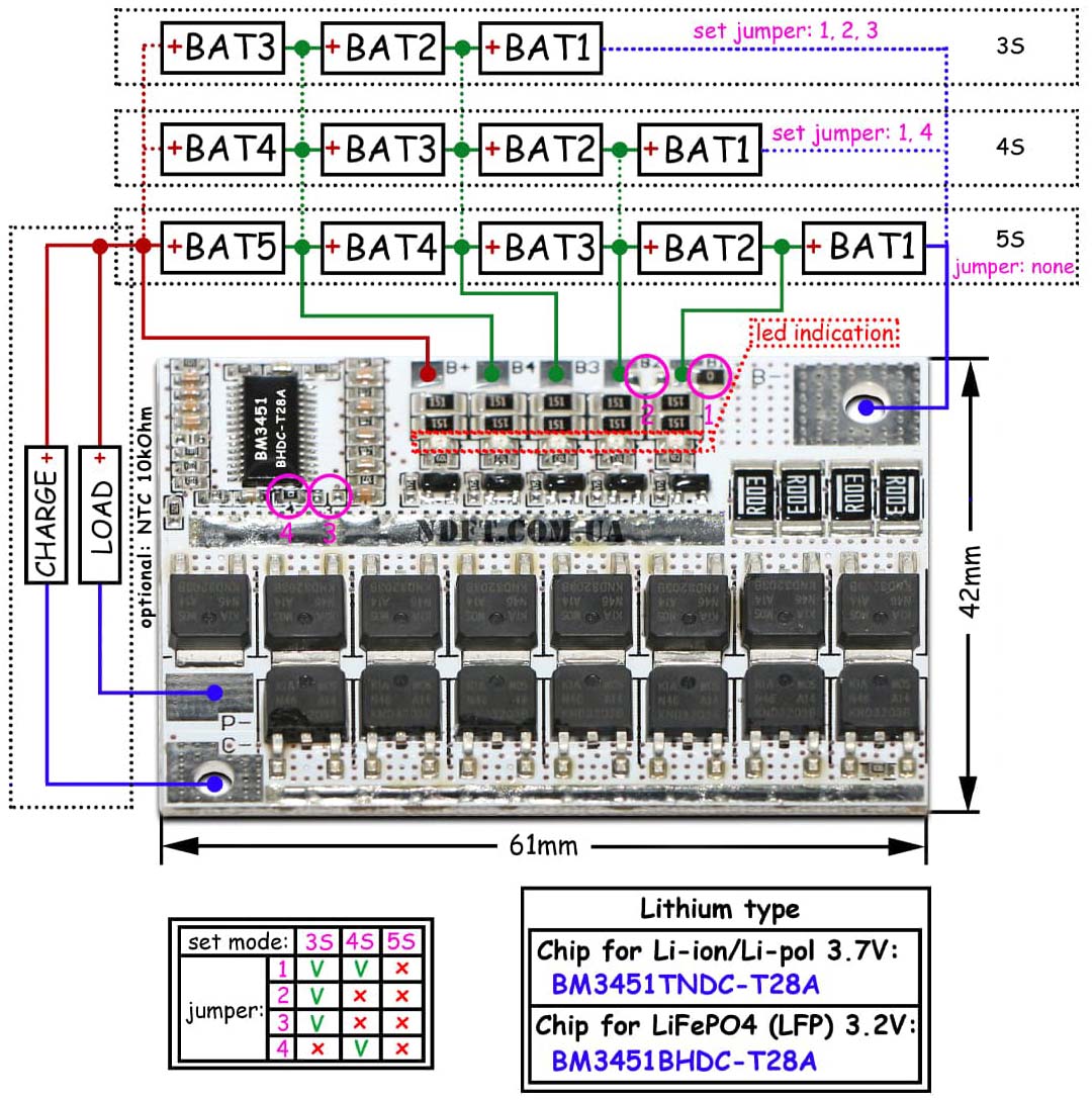 Fig. 8 BMS controller 3-5S for lithium batteries with balancing
Of course, if you have lithium-iron-phosphate (LiFePO4) cells, then you need to take a BMS controller specifically for them. The controllers differ only in the type of microcircuit. For Li-Ion and Li-Pol there is BM3451TNDS-T28A, for LiFePO4 there is BM3451BHDS-T28A, it is important not to confuse them.
- The step-down converter U4 is the same as U2, and can be found in online stores by searching for “Step-down module DC-DC 20A 6~40V, 1.2~36V with current and voltage regulation.” It's preliminary setting to at least the output voltage is required. The appearance of the applied step-down converter is shown in fig. 3
- The U5 boost converter can be found in online stores by searching for "TL494 400W Boost Converter with Voltage and Current Regulation". It's preliminary setting to at least the output voltage is required.
The appearance of the applied boost converter is shown in fig. 9
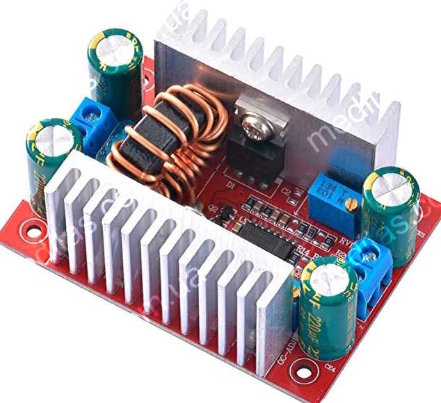 Fig. 9 Step up DC-DC converter in TL494, Uin-8.5~50V, Uout-10~60V, 400W, with voltage and current adjustment
- All field effect transistors can be used IRF510, IRF520, IRF540, IRF610, IRF614, IRF620, IRF630 and many others. There is no need to use all of the same types; differences are possible. At the charging station, in the photo, BS170 is generally used because it came to hand.
- As a battery switch, S1 must be used with sufficient switching current, for example, a KN-402 toggle switch or a KCD7-302 key switch, connecting all groups in parallel.
- Protection diode D6 for a current of at least 10A, for example from the ancient times of the USSR D214A, D215A, D242A, D243A, D245A. No need to put it on the radiator.
- The charging diode D1 is needed to automatically turn on the digital voltmeter DV1 with fans, and also to ensure that the batteries are not discharged through the charging converter U2. If it is excluded, then during a loss of 220V mains voltage, the battery will be additionally discharged through output U2. It is better to choose a diode from the Schottky series; it has a lower forward voltage drop, with a maximum voltage of at least 30 V and a maximum current of 10-40A (preferably more). If you select a diode from the ancient D214A, D215A, D242A, D243A, or D245A, then the output voltage of the charging converter U2 should be about 17.2 - 17.4 volts, if it is a Schottky diode, for example, 30D40PT, 30CPQ060, PBYR1540CT, PBYR1540CT, STPS2045CT, then The output voltage of U2 in the unloaded state should be about 17.0 volts. If the charging current is less than 5 amperes, it is not necessary to place the diode on the radiator; if it is 5-10 amperes, then the diode must be placed on a small radiator, which can be an aluminum plate with a thickness of 1 - 4 mm and a surface area of 30-100 cm square. The greater the charge current, the larger the surface area of the radiator.
- Diodes D2 - D5 - low-power (signal), 1N4148, KD220, KD223, KD509, KD510, KD513, KD521, KD522 with any letters.
- 12-volt fans from old computer power supplies, preferably identical ones.
| Ориентировочные цены на комплектующие в ноябре 2022г. | ||
|---|---|---|
| Сетевой бескорпусный блок питания на 24В 6А WX-DC2416 | 380 грн. | 1 шт. |
| Понижающий преобразователь с регулировкой напряжения и тока | 180 грн. | 2 шт. |
| Повышающий преобразователь на TL494 (для выхода на 19 В) | 220 грн. | 1 шт. |
| BMS (Battery Management System) контроллер 3-5S с балансировкой | 80 грн. | 1 шт. |
| Цифровой вольтметр высотой цифр 0,28'' | 40 грн. | 4 шт. = 160 |
| Цифровой вольтметр высотой цифр 0,36'' | 55 грн. | 1 шт. |
| Разъёмы XT-90 папа-мама | 50 грн. | 1 набор |
| Разъёмы XT-30 папа-мама | 10 грн. | 1 набор |
| Тумблер KN-402 (для переключения аккумулятора внутренний - внешний) | 150 грн. | 1 шт. |
| Клавишный выключатель выходов | 15 грн. | 3 шт. |
| Термопредохранитель 10 А 85 град. | 10 грн. | 5 шт. |
| Услуги почты около | 170 грн. | |
| Наверняка что-то забыл, поэтому закладываю ещё 170 грн (а, скорее для ровного счёта) | 170 грн. | 1 шт. |
| Всего | 1900 грн. | |
Getinaks panels, studs, nuts, etc. from garage scrap. The wires are from old computer power supplies, a diode, a switch, plugs, and connectors from disassembly, but if they are not there, then they are mere trifles.
Preparing for assembly
Before assembly, you should preconfigure the BMS controller U3, charging converter U2, and output converters U4 and U5.
- Preparation of the BMS controller U3 consists of installing and removing jumpers 1-4 in accordance with the number of battery cells of the charging station connected in series (for the described charging station this is 4S), see fig. 8. A BMS controller is not needed if lead-based batteries (lead-acid, gel, or AGM), as well as NiCd and NiMH are used. For LiFePO4 and Li-ion - Li-pol, a corresponding BMS controller is required.
- The charging converter U2 is configured depending on the batteries used.
Its output voltage is set approximately from the calculation (final charge voltage per element)*(number of elements connected in series (quantity S))+(voltage drop across diode D1). For most batteries, the final charge voltage per cell for Li-ion and Li-pol = 4.2 volts, for LiFePO4 = 3.7 volts, for NiCd and NiMH = 1.38 volts, and for lead chemistry (lead-acid, gel or AGM) = 2.3 volts. The voltage drop across diode D1 depends on the type of diode, the current flowing through it, and its temperature. For ordinary high-power diodes this is about 0.6 volts, for Schottky diodes it is about 0.2 volts. In the described charging station, the voltage at output U2 was set to 4.2 * 4 + 0.6 = 17.4 volts. Then, during operation, this voltage was reduced to 17.2 volts.
Its output limiting current is set in the range from 0.1C to 0.2C, where C is the capacity of the battery pack being charged. If the accumulator is lead chemistry (lead-acid, gel, or AGM), the recommended charge current is 0.1C. If LiFePO4 is used, the charge current can be increased to 1C. In the case of using Li-ion, Li-pol, NiCd, and NiMH batteries, the charge current can be in the range of 0.3 - 0.5 C. In any case, the charge current should not go beyond 0.1 C - 1 C. The higher the charge current, the shorter the battery life, but the faster the charging occurs. For the charging station described here, the charging current was set to 4 amps.
- Converters for end users are configured following the wishes of the operator. For the described charging station, the USB converter was set to 5 volts 3 amps, the laptop power converter was set to 19 volts 3 amps. For a USB converter, do not calculate a current greater than 2 amps per outlet.
Assembling
The battery packs are connected to the already assembled charging station, i.e. last, after the installation has been thoroughly checked, especially for the absence of short circuits in the battery circuit.
Because the voltages on the corresponding groups of parallel wired cells of the battery packs may be different, it is advisable to connect them one at a time and through an equalizer, the diagram and photo of which are shown in fig. 10. We recommend to connect the first battery pack directly to the charging station, and the second through an equalizer. We wait several hours (we left it overnight) until the voltages are equal and reconnect the second battery pack directly, and the 3rd through the equalizer, wait again, etc., until all batteries are connected directly to the charging station.
Diagram and appearance of the voltage equalizer shown in fig. 10
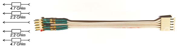 Fig. 10 Voltage equalizer. Scheme and appearance.
If you connect without equalizing the voltage, then if the voltages on the groups of parallel wired cells are very different, the batteries may heat up with their failure, self-ignition, and even explosion. This primarily concerns Li-Ion and Li-Pol elements. After all battery packs are connected, we recommend equalizing the groups of parallel wired cells voltages using an external source. We recommend determining the group of parallel wired cells with the highest voltage and charging the rest to its level. The fact is that the balancer on this BMS controller is quite weak and will balance all the batteries over a large number of charge-discharge cycles, and before that the batteries will not be able to operate at full capacity. If it is assumed that there will be quite a lot of elements in the battery of the charging station, then it is advisable to use a more advanced BMS controller with an active balancer, which will have an effect but will cost a little more.
Troubleshooting and application details
A correctly assembled charging station from preconfigured blocks will already be operational.
One of the most common nuances in work can be described as follows:
- during the charging process it is interrupted, the DV1 voltmeter goes out and the fans stop. The reason is that groups of parallel wired cells of the battery pack are unbalanced and / or the voltage is set too high at the output of the charging converter U2. The BMS controller, therefore, turns off the charging current to avoid overcharging. Troubleshooting should begin by checking the balancing of the groups of parallel wired cells of the battery pack. The voltages on the of the groups of parallel wired cells should not differ from each other by more than 0.02 volts. To reduce the difference in voltages, we recommend recharging the groups of parallel wired cells, where the voltages are lower, with an external power supply. The BMS controller has its own indication - red LEDs light up in those groups of parallel wired cells where the voltage is higher, thus indicating voltage suppression. Actually, this is passive balancing. For more efficient balancing, there are BMS controllers with active balancing that do not use resistors to dampen voltage, but pump energy from the groups of parallel wired cells where the voltage is high to where it is lower. An example of such a BMS controller for 4S LiFePO4 batteries is DL4S-40A. If the groups of parallel wired cells are balanced, but the BMS controller still interrupts charging, the controller may not match the battery type, see fig. 8. If it is, you should check the output voltage of the charging converter U2 in an unloaded state, if it is approximately the same, then there may be less voltage drop across diode D1 than expected. In this case, it is worth reducing the voltage at the output of the charging converter U2 in an unloaded state by about 0.1 volts. If the response of the BMS controller has not changed, you should further reduce the voltage at the output. U2 by 0.1 volt and so on until the BMS controller stops turning off the battery at the end of the charge.
- the laptop is connected and working, but its battery is not charging.
A possible reason is that the laptop manufacturer uses chipping of the network adapter. Only a chipped adapter will be able to charge the battery of such a laptop. Manufacturers saw chipping adapters - Dell, Sony. A possible solution is to buy a faulty adapter for your laptop on the radio market and install the chip in the charging station. In this case, the output to the laptop will be 3-wire.
- The USB adapter is set to 5 volts 20 amperes, and charging the smartphone takes much longer than 20 minutes.
The reason is similar to the previous one, “fast” chargers also “negotiate” with consumers about the “speed” of charging. Due to the insignificance of the problem, no solution was sought.
- while charging the battery (only the internal battery is charged by the built-in charger), the voltage voltmeter on the battery is automatically turned on only in the position of the switch to the internal battery.
This is an operating feature that allows you to simultaneously charge the internal battery, and operate the output converters U4-U6 from an external one. Then the voltmeter will show the voltage of the external battery, i.e. the one from which the output converters operate. There is a variant of the circuit where, if the voltage of the external battery is below the minimum, and the battery switch is in the “external” position, then the red LED lights up, signaling the unsuitability of the battery and the main voltmeter, if charging is in progress, shows the voltage on the internal battery. This complicated the circuit and design and is therefore not included in this article.
Ways to reduce the cost and simplify the design
To reduce the cost of the design, instead of the 24V network stabilized power supply WX-DC2412, you can use another one with a 24V 3-5A output, or even use an unstabilized power source, which is a network transformer with a primary winding of 220 Volts and a secondary winding of 17 - 22 volts, with a rectifier and a smoothing capacitor of at least 2000uF x 50V (better 5000 - 10000uF), look fig. 11. In any case, the charge mode will be observed on the U2 converter.
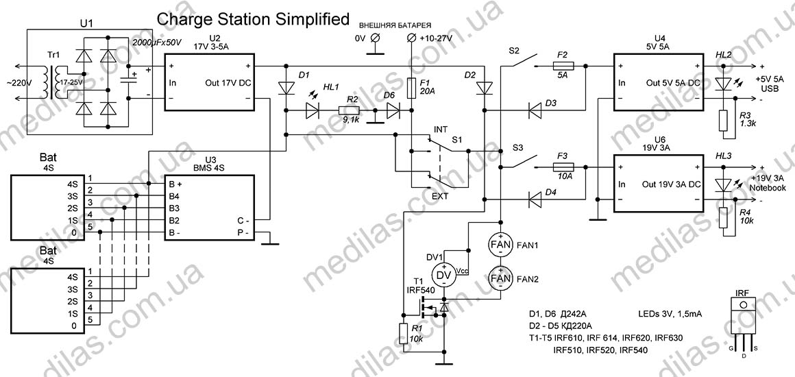 Fig. 11 Circuit of a simplified charging station without additional voltmeters and with a power transformer in U1
You can also exclude voltmeters DV2-DV5 (with field switches T2-T5) from the circuit, especially if the cells for the battery are new or selected for the same group of parallel wired cells capacity. In any case, the BMS controller will try to balance the groups of parallel wired cells and if the imbalance is serious, it will turn off the charging or load.
The proposed BMS controller is quite simple, but at the same time it has its balancing indication, which you can also focus on.
Ways to improve and retrofit the structure
It should be understood that the author first wanted to share the principles of construction and experience in creating charging stations, and then only a description of the finished design.
For example, according to this principle, an office charging station was created with only an external battery on 2 12-volt LiFePO4 (lithium-iron-phosphate) batteries 100 A/h, a total of 24 volts, with an inverter power supply of 4800 W, up to 4 laptops, USB x 5, LED lighting strip 12 volt 5 ampere, JPON - 12 volt modem and 9 volt router. It did not have a BMS controller, since it is built into the batteries, there was only 1 voltmeter showing the total voltage, by which you can navigate the battery charge level. Both charging converters U1 and U2 together served as one modified industrial power supply S-720-36 at 36 volts 20 amperes, whose output voltage was reduced to 33.5 volts by adjustment and the charge also went through a double Schottky diode D1, The current limit was reduced to 15 amperes. To power laptops, 2 converters of 800 watts each were used, etc., but the original principle remained the same.
Also, if you use a lead-based electrochemical system (lead-acid, gel, or AGM batteries), it is critical to prevent them from being over-discharged to maintain their performance. To do this, such a system can be retrofitted with an alarm and/or a voltage cut-off in case of a drop to a certain level.
In general, the versatility of the platform allows you to build systems limited only by the finances and imagination of the master.
- Details
- Hits: 1618
A practical design of an inexpensive and efficient Power Bank is presented for quick self-assembly, providing uninterrupted Internet access
The task was to assemble a simple power system for a GPON modem and a Wi-Fi router with charging from the mains, as autonomous as possible, corresponding to the “plug and forget” principle, at minimal cost, quickly, and adaptable to any type of the rechargeable battery. Other conditions were maximum efficiency when powered by batteries and availability of parts.
To simplify and speed up assembly, it was decided to assemble a powerbank using commercially available ready-made modules.
Principles of constructing uninterruptible power supplies
The principle of on-line construction was chosen, when consumers are powered through converters from batteries, the batteries are charged and the voltage on them is maintained according to the presence of voltage in the mains. It is this construction topology that has maximum efficiency when powered by a battery and satisfies the “plug and forget” operating principle. Another important advantage is the ability to build and easily adapt to any type of battery. For example, one of the options was built and worked perfectly on a gel battery with one closed can! This “unpretentiousness” to batteries allows you to use (after selection) even those that are left in workshops for repacking batteries, and really, in each such service center, every working day there are 10-30 cells that have lost their capacity but are still suitable.
Another topology based on a purchased UPS (Uninterruptible Power Supply) is MUCH less economical and costs more, although it is easier to implement. In other words, a battery from the same UPS, but connected to an on-line circuit, can last the same consumers tens of times longer than when working in its own UPS. This is explained by the fact that converting from 12 Volts to 220 AC, and then back to 12 and 9 Volts is MUCH less economical than converting similar DC voltages.
Another option for constructing an uninterruptible power supply circuit is to use a USB powerbank with boost converters attached to it to power the modem and router. In terms of efficiency, this is much better than the option of using a UPS, but it has its own suboptimalities. In addition, a USB power bank is sometimes needed to solve other issues.
Description of design
Powerbank schematic diagram
The design of the specific powerbank described is based on the following:
- On-line topology, “plug and forget” principle
- Power supply for Wi-Fi router - 9V, 200mA
- GPON modem power supply - 12V, 200mA
- The presence of a large number of battery cells GP 380AFH, asking for recycling.
I read somewhere on the forums that TP-Link routers with a 9V power supply can also be powered with 12V, but I didn’t want to check, risking burning the router. Based on this, and also to ensure maximum efficiency when powered by batteries, it was decided to use 2 ready-made pulse stabilizing converters.
Powerbank inner view and component placement
Prices for components for November 2022:
- Unpackaged power supply for 220V AC 24V DC WX-DC2412 9.25 US$.
- Buck converter with voltage and current regulation for XL4015E1 (for charging circuit) 2.75 US$.
- Buck converter with voltage regulation on XL4005 (for 9V output) 1.7 US$.
- Boost-buck converter for XL6019 (for 12V output) 3.5 US$.
- Digital voltmeter 2.7 US$
- Post services about 3.75 US$.
- Total 23.65 US$.
All parts are readily available and can be purchased at your local radio market or online.
Electronic modules placement
The batteries were collected from a tank for used batteries, which were not handed over to the collection point due to lack of time. This is how useful it can be to collect used batteries for recycling). Of about 150 NiMH GP 380AFH elements, the best 50 were selected based on capacity and assembled into blocks of 10 pieces for 12 volts. The selection was made using Opus BT-C3100 and SkyRC MC3000 chargers, powered directly from a 12-volt battery to ensure uninterrupted operation. Opus BT-C3100 turned out to be more effective for selecting these specific elements than SkyRC MC3000, although the first is considered household, and the second is professional.
Powerbank rechargeable batteries pack made of NiMH GP 380AFH x 50
A 10A 85-degree thermal fuse is installed inside each block. (not shown in the diagram). Blocks of 10 pieces were mechanically fastened to each other using transparent silicone and Moment-Crystal glue with a gap of 4-5 mm between them for cooling. Despite the selection of elements, a significant scatter of characteristics was observed both in capacity and internal resistance. Therefore, it was decided to connect all the corresponding elements of each block in parallel. This idea arose at the selection stage, so elements were selected into blocks so that an element with a lower capacity would be parallel to an element with a larger capacity. Since the charge-discharge currents are small, it was decided to neglect the selection based on internal resistance.
Powerbank side view
Powerbank appearance
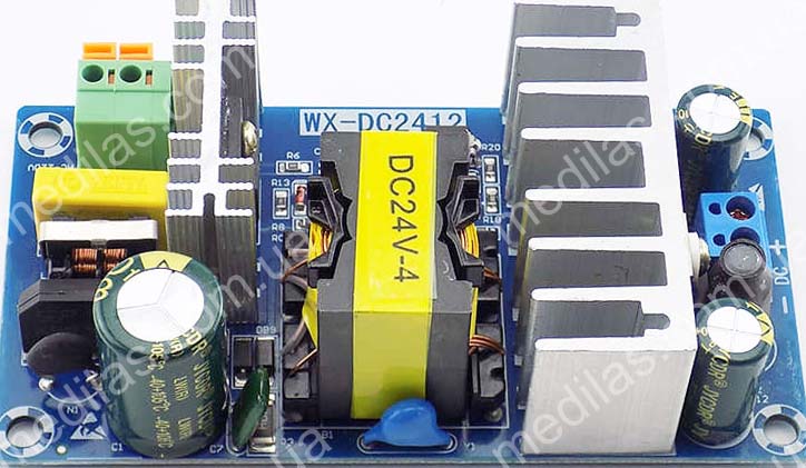
U1 Power supply unit WX-DC2412 220V AC to 24V DC 4A max
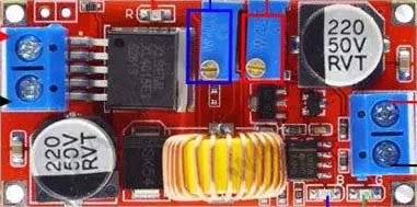
U2 Step down converter used as the battery charger. It lets adjust the output voltage and maximal current. The potentiometer in red sets the current, in blue, and accordingly adjusts the output voltage.
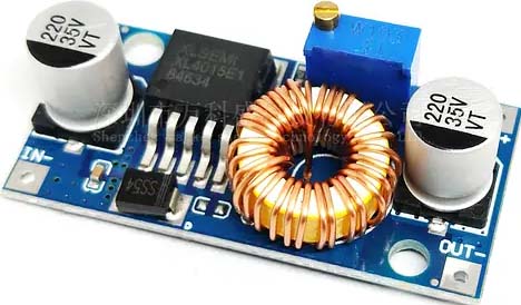
U3 Cheap step down converter with output voltage adjustment
U4 Step up-down converter with output voltage adjustment
The output voltage of the converter U2 was set to 14.1 volts, the maximum current is 1.5A, which corresponds to a battery charging current of about 1.1A.
Plastic panels, studs, nuts, etc. from garage scrap. The wires are from old computer power supplies, a diode, a switch, plugs, and connectors from disassembly, but if they are not there, then they are mere trifles in radio stores.
The plugs to the router and modem are the same 5.5x1.5 with a plus in the middle and a minus on the outside.
Practice has shown that a full battery charge is enough for more than 24 hours of continuous operation.
This is a description of the NiMH battery design using GP 380AFH cells.
Another design was assembled using LiFePO4 elements.
Powerbank made of 3 x 4S LiFePO4
If longer battery life is required, you can connect additional 12V batteries in parallel with the main one or select a battery with a larger capacity. You can even connect a car battery (the current of the step-down charging converter can be increased to 3A and more), or you can use a “dead” battery that no longer cranks the starter. An acquaintance made a powerbank using this “recipe” and connected it to a car battery that had served for about 5 years, with 1 cell shorted, and says it is enough for about 15 hours of continuous operation.
Battery selection
The battery can be installed gel or AGM, same as for uninterruptible power supplies, 12V, 7-9-12 A/h. You can also use a classic lead acid, gel, or AGM battery with a sprinkled (shorted) 1 cell. And, of course, you can use 4S (4 series-connected elements) LiFePO4 and Li-Ion - Li-Pol batteries from selected elements, but in this case, the selection is stricter and the use of a BMS (battery management system) (balancer, balancing board) is mandatory. Li-Ion - Li-Pol batteries can be obtained from workshops that repack batteries for laptops and power tools. If several batteries are used, they must all be powered by the same electrochemical system. If, say, a lead battery with a shorted cell is used, then in parallel to it for amplification, you can connect the same lead battery with a shorted cell. You can even use 6 Volt batteries, but in this case, the converters U3 and U4 must be boost converters. In one article it is difficult to describe all possible options for using batteries in such an uninterruptible power supply. In all cases, it is necessary to adjust the voltage of the charging unit (converter U2).
Approximate output voltages of converter U2
| Battery | Converter U2 output voltage | |
|---|---|---|
| D1 non Schottky | D1 Schottky | |
| Lead, gel or AGM, 12V all cells work | 14,2 - 14,4 | 13,9 - 14,1 |
| Lead, gel or AGM, 12V 1 cell shorted | 12,0 - 12,2 | 11,7 - 11,9 |
| NiMH, NiCd 10S | 14,2 - 14,4 | 13,9 - 14,1 |
| LiFePO4 4S | 14,4 - 14,6 | 14,1 - 14,3 |
| Li-Ion, Li-Pol 4S | 17,0 - 17,5 | 16,6 - 17,1 |
| Li-Ion, Li-Pol 3S | 12,9 - 13,3 | 12,5 - 12,9 |
* the number before S means the number of elements connected in series.
If a Schottky diode is used as D1, the voltage at the output of the converter must be reduced by approximately 0.4 V. To avoid excesses with batteries and load (modem + router), all converters must be configured before being included in the power bank. Confusing + and - is strictly prohibited.
Setting the limiting current of the charge converter U2 corresponds to the principle that the larger the battery capacity, the higher the current the charge converter U2 can be set to. Battery charging current = limiting current of the converter U2 minus current consumption of the load (modem + router) through the converters. It is not advisable to reduce the charge current below 0.1C and should not be higher than 1C, where C is the battery capacity. The higher the charge current, the faster the batteries charge and the faster they lose capacity during operation. If the charging current is too low, there is a risk that the battery will not have time to charge during the short time of electricity availability. There is an opinion that some average optimal charging current for lead, gel and AGM is 0.2C, for example, for a 12V 7A/h battery the optimal charging current will be 1.4A, and for other types of batteries 0.3C.
It should be remembered that car unsealed lead-acid batteries emit harmful gases during operation, so it is better to place them in ventilated areas. To significantly reduce the emission of gases, as well as to extend the service life of such a battery, it should be operated in the temperature range of 10-25oС, charged with a current of no more than 0.1 C to a voltage of no more than 14.3 V and discharged no deeper than 10-11V.
You should also follow the operating rules for the corresponding batteries, the main ones of which are: do not heat above 60oС, do not allow polarity reversal, short circuit, overcharge, and overdischarge.
Diode D1 (in the described design a Schottky diode SB340 is used) is needed to ensure that the batteries are not discharged through the charging converter U2 and the power supply. If it is excluded, then during a loss of 220V mains voltage, the battery will be additionally discharged through the charging circuits with a current of about 30 mA. This will reduce its uptime by 7-8%. It is better to choose a Schottky diode as a diode; it has a lower forward voltage drop, with a maximum voltage of at least 30 V and a maximum current of 3-6A (preferably more). Diodes recommended for use as D1: Schottky: 1N5844, SB340, SB350, SB540, SB550, 1N5822 Non Schottky: FR601 - FR607, FR501 - FR507
Ajustment
The adjustment is simple and consists of the following:
- Adjustment of modules U2, U3, and U4 is carried out before installation in the power bank circuit.
- The voltage at the output of the step-down charging converter U2 depends on the battery used and is approximately set following the table given above. The output current limitation of the step-down charging converter U2 depends on the capacity of the battery used and is described here.
- Converters U3 and U4 are adjusted to the voltages required by specific consumers (modem and router).
This completes the adjustment.
Assembling
Assembling is carried out after adjusting modules U2, U3, and U4. The assembled power bank should be carefully checked for polarity reversals and short circuits, and only then connected to the battery and plugged into the network. It should be remembered that electronics do not forgive polarity reversals.
This type of powerbank can also be used for video surveillance systems, to power home routers and modems, and ethernet provider switches to ensure uninterrupted wired Internet. In this case, you can simplify the design by eliminating one of the buck converters.
Ways to reduce the cost, simplify and modernize the design
To reduce the cost of the design, you can use a linear voltage regulator LM7809 instead of the U4 step-down converter. This solution will slightly reduce the efficiency when powered by batteries. If 4S Li-ion or Li-pol is used as a battery, then instead of U3 it is advisable to use not a step-up or step-down converter, but a cheaper step-down converter or even a linear voltage regulator LM7812. Instead of the 24V network stabilized power supply WX-DC2412, you can use another one with a 24V 3-4A output, or even use an unstabilized power supply, which is a network transformer with a primary winding of 220 Volts and a secondary winding of 15 - 20 Volts, with a rectifier and a smoothing capacitor not less than 1000uF x 50V. In this case, stabilization will be on the U2 converter. If a lead, gel, AGM, or NiMH, NiCd battery is used (without a BMS controller), it makes sense to assemble a load cut-off device based on the minimum specified voltage on the batteries. This can significantly extend the life of the batteries.
It was also noticed that the recommended charging converter U2, with a set charge current of more than 1 A, gets quite hot (but still works). The reason is its choke. If a charging current of more than 1 A is required, it is desirable, and when setting a charging current of more than 2 A, it is necessary to either select another, more powerful converter with current and voltage regulation or modify this one by rewinding the inductor with a slightly thicker wire and increasing the number of turns by 20%. You can also install a common-mode choke taken from disassembling an ATX computer unit instead of the original choke.
The design described above provides great opportunities for modernization, both in terms of increasing the battery capacity and adding new functions. For example, you can turn a power bank into a charging station by making outputs for USB and/or for a laptop or other gadget you use.
To organize USB charging, you need a step-down converter set to 5 volts 3 amperes.
Step down DC-DC converter in LM25116, Uin-6~40V, Uout-1.2~36V, 20A, with voltage and current adjustment
It should be connected to the battery through a fuse and a switch. You can connect 2 USB sockets to its output, which can easily be found on the radio market or in online stores. We install sockets from disassembled old motherboards. Another LED (via a resistor) can be connected to the output of the converter to indicate the presence of voltage at the USB output.
The same converter (configured accordingly as described above) is recommended to be used as charger U2 if the battery capacity exceeds 10 A/h.
Using the same principle, you can make an output for powering a laptop (usually 19 or 21 volts), for this you will need a boost converter configured for the appropriate output voltage and current of 5-10 amperes.
Step up DC-DC converter in TL494, Uin-8.5~50V, Uout-10~60V, 400W, with voltage and current adjustment
It should also be connected to the circuit via a fuse and a switch. We recommend making the output using a pair of female-male XT30 connectors, joining the male connector to a purchased cable with a laptop power connector. Such a cable can also be found on the radio market or in online stores.
Another idea is to equip the power bank with a lighting LED or strip in the same way.
Therefore, we recommend that if you plan to work with high-capacity batteries, leave some space for additional converters and your fantasy.
Instead of a conclusion
With this article, the author wanted to share not so much the finished design as the principles and ideas underlying it.
You should also understand that uninterrupted Internet will be guaranteed if you use GPON (Gigabit Passive Optical Network) (fiber optic) data transmission technology. This technology directly connects the provider and the user and does not require intermediate routers and switches. In the case of using a wired communication channel over twisted pair, intermediate routers, and switches are required, which also require an uninterrupted power supply. Typically, providers do not bother to ensure uninterrupted power supply to equipment located outside their premises. This leads to the fact that if there is no power supply along the signal path between the provider and you, even if the power supply to your router is uninterrupted, there will be no Internet access. After all, along the path of a signal traveling over a twisted pair cable, there will be dozens of switches, hubs, and routers that also require power. In other words, if you have wired Internet, then to ensure uninterrupted access you need to switch to GPON (fiber optic). To do this, it is usually enough to leave a request with your provider.
- Details
- Hits: 6639
Working with the probe has significantly changed our
understanding of electrolytic capacitors,
their quality and manufacturers...
One of the most unreliable radio elements in electronic equipment has been and remains an electrolytic capacitor. The most common cause of failure is the "drying out" of the electrolyte, which leads to an increase in the ESR (equivalent series resistance) of the equivalent series resistance (ERS). When measuring only the capacitance of a "dried" capacitor, the difference with a serviceable one is practically not visible. In addition, in most cases, capacitance measurement will require removing the capacitor from the circuit, which is not always convenient, and the soldering-soldering process adversely affects the capacitors themselves.
Based on the experience of designing and operating similar devices, here is comparison of devices various types and formats for measuring and indicating the equivalent series resistance (ESR) of electrolytic capacitors.
The requirements underlying the development of our electrolytic capacitor tester - Equivalent Series Resistance Indicator:
1. Possibility to check capacitors without soldering out of the circuits.
1.1 To reduce the influence of the circuit in which the electrolyte is located, not to harm it, and at the same time to minimize its influence on the measurement accuracy, the voltage on the open probes should not exceed 200 mV (less than opening semiconductor np junctions).
2. Portability, convenience, practicality.
2.1 The device should be made in the form of a probe, because there is no need to accurately measure the ESR, a measurement error of 20 - 30% is quite satisfactory. By the way, from experience - heating an electrolytic capacitor from room temperature to finger temperature (33-35 OC) lowers ESR by an average of 1.5 times. Accurate measurement of ESR is justified only in the conditions of plants producing electrolytic capacitors, for the monitoring of products. And the reaction speed to the LED indication is much faster than to the display numbers. At the same time, in order to expand the measuring range, a logarithmic indication is preferable to a linear one. The logarithmic indication allows to cover a wider dynamic range on the same number of LEDs than the linear one.
2.2 The device must be rechargeable with an autonomy of at least 8 hours. This is enough to use the device for field work, without carrying an adapter with you on business trips, which, by the way, weighs more than the device itself.
2.3 Protection against the charge of the measured capacitor. The probe must not be damaged or damage must be minimal if the measured capacitor is charged.
3. To ensure adequate accuracy and eliminate the dependence of the indication on capacitance, a synchronous detector must be present in the circuit.
4. The measurement frequency should be between 30 - 200 kHz.
Probe - meter - indicator of equivalent series resistance (ESR, ESR) of electrolytic capacitors. Specifications of the latest version of the instrument
The device is designed to evaluate the ESR (equivalent series resistance, equivalent series resistance, ESR) of electrolytic capacitors without soldering (disconnecting) from the circuits.
AC voltage on open probes is not more than 200 mV, which eliminates the influence of external circuits on readings device, and the induced voltage will not damage external circuits.
Measurement frequency 100 kHz +- 20%
Range of the estimated ESR 0.1 - 5.0 Ohm.
LED indication with a logarithmic scale. The number of indication LEDs is 10.
The range of capacitances of the tested capacitors is from 0.1 μF or more.
When connected, it withstands the discharge of capacitors up to 50 V.
Powered by a built-in Li-ion battery.
A full charge of the battery lasts for 10 hours of continuous operation of the device.
The duration of a full charge is no more than 3 hours.
The charging control circuit is built into the device.
Charging adapter - from Nokia mobile devices of the old type (type ACP-7E 3.7V 355mA 1.3VA).
Probe - meter - indicator of ESR (equivalent series resistance, ESR) of electrolytic capacitors. Simplified design (prototype) of a device for testing electrolytic capacitors.
Simplicity of the design of the probe and efficiency in operation, has already been verified by 10 years of operating experience both in the workshop and on the road. The device for testing electrolytic capacitors proposed for repetition does not contain microcontrollers and is assembled on available common parts.
The device is designed to evaluate the ESR (equivalent series resistance, equivalent series resistance, ESR) of electrolytic capacitors without soldering (disconnecting) from the circuits.
AC voltage on open probes is not more than 200 mV.
Measurement frequency 40 kHz +- 20%
The estimated ESR range of 0.2 - 5.0 Ohm is divided into 2 subranges 0.2 - 1.0 Ohm and 1.0 - 5.0 Ohm.< br />LED display with logarithmic scale. The number of indication LEDs is 5.
The range of capacitances of the tested capacitors is from 1.0 μF or more.
When connected, it withstands the discharge of capacitors with a voltage of up to 300 V.
Power is supplied from a built-in Ni-Cd battery with a nominal voltage of 3 .6 V, 80 mAh.
A full charge of the battery lasts for 6 hours of continuous operation of the device.
The duration of a full charge is no more than 3 hours.
The charging control circuit is built into the device.
Charging adapter - from old-style Nokia mobile devices (type ACP-7E 3.7V 355mA 1.3VA).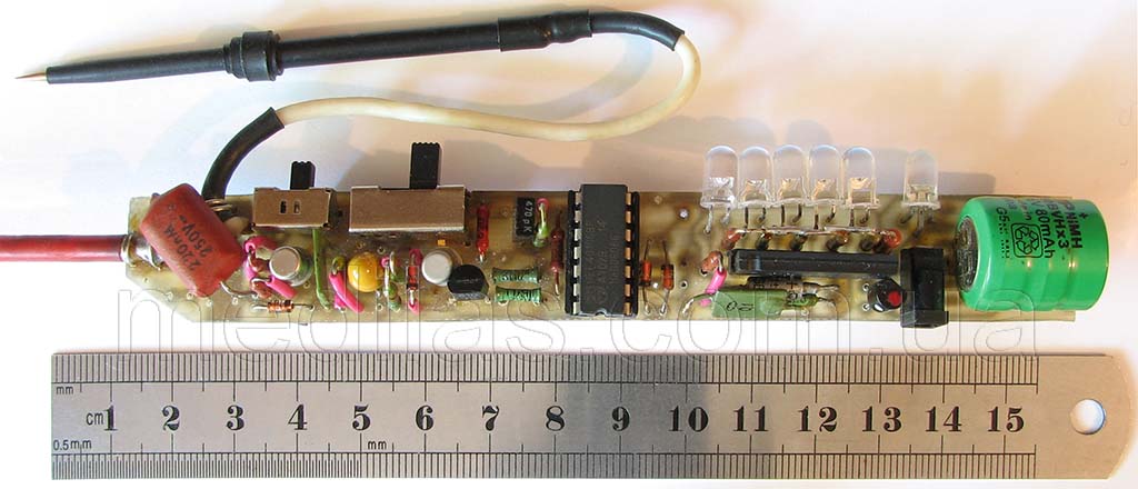
Fig.2 Appearance of the finished design of the probe - ESR indicator of electrolytic capacitors.
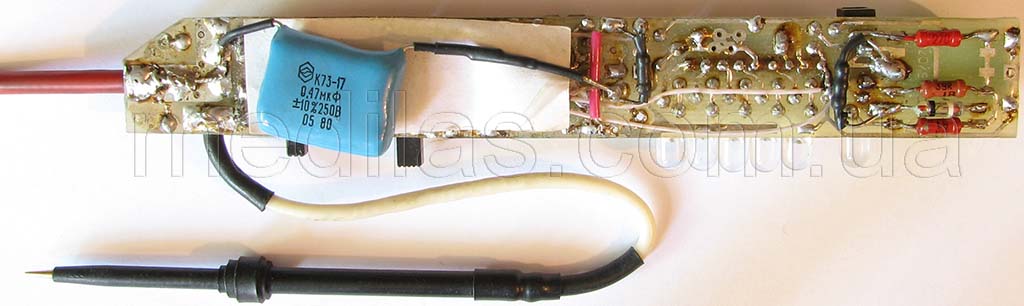
Fig.3 View of the device for testing electrolytic capacitors from the side of the printed circuit board.
Fig.4 Structural diagram of the probe - ESR indicator of electrolytic capacitors. frequency of 35-40 kHz, a limiter to prevent damage if the measured capacitor is charged, a high frequency switchable gain amplifier, a detector, an indicator, a voltage regulator and a battery with a charge circuit.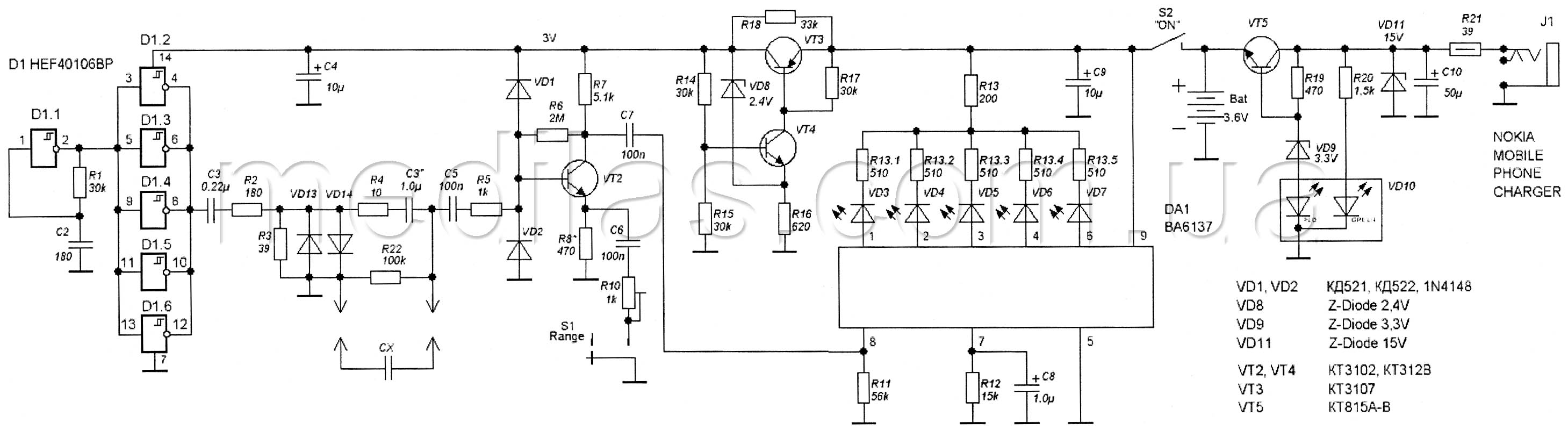
Fig.5 Schematic diagram of the probe - ESR indicator of electrolytic capacitors.
The master oscillator is made on a CMOS chip (CMOS) D1 40106 - 6 Schmidt triggers, which made it possible to simplify the circuit and include 5 elements as an output buffer.This solution made it possible to leave the output current sufficient, because of It is known that at a minimum supply voltage, the buffer properties of CMOS elements, as well as any other ones, also fall to a minimum. Resistors R2 and R3 form a divider that determines the output voltage across the open probes. Diodes VD13, VD14 protect the outputs of the D1 chip from getting voltages between the probes due to measurements of capacitors that “turned out to be” charged, or during “accidental” inclusion in the working circuit. High-frequency amplifier diodes VD1, VD2 and resistor R5 protect against similar cases.
The high-frequency amplifier is made on the transistor VT2, and serves to increase sensitivity when measuring low values of equivalent series resistance. In order to provide measurement over the ESR range of 0.2 - 5.0 ohms using a 5-LED logarithmic indicator, the range was divided into 2 sub-ranges. Switching between subbands is performed by switch S1, which changes the gain of the high frequency amplifier (UHF). The UHF gain on the sub-range 1.0 - 5.0 Ohm is approximately 5 and is regulated by the selection of R8, and on the sub-range 0.2 - 1.0 Ohm it is approximately 25 and is regulated by a miniature tuning resistor (trim) R10. With the same resistor, in the process of adjustment, we achieve alignment of the subranges.
The indicator is made on the DA1 BA6137 chip (complete direct analogues of NTE1866, KA2285B, LB1423N, AN6884, GL1223), which is a driver of 5 LEDs. The microcircuit includes an active amplitude detector, a DC amplifier, a set of comparators and LED control switches with current limiters. The chip provides a logarithmic level indication. Resistor R13 is designed to reduce the level of consumption by the LEDs when the probes are not connected and all the LEDs are on.
Now a few words about choosing the operating frequency of the device. These microcircuits are designed to indicate the level of an audio frequency signal and contain an active amplitude detector. At least with the BA6137 chip, at input frequencies above 40 kHz, there was a discrepancy between the signal level and the number of on / off LEDs. For example, at a frequency of 45 kHz and ESR = 1 Ohm, only 1 LED lights up, ESR = 1.8 Ohm - 2 LEDs (that's right), and if ESR = 5.0 Ohm, everything that corresponded to ESR < 1 ohm, which will eventually lead to the definition of a faulty capacitor as a good one. On the other hand, in order to reduce the effect of capacitance on the readings, it is advisable to choose a higher frequency (100 - 200 kHz). Therefore, the operating frequency must be selected as high as possible, at which the compliance of the instrument readings is maintained. To calibrate and check compliance with the level scale, non-inductive resistances, for example, the MON type, can be used as an ESR source. The advantage of such a regulator circuit is a high stabilization factor and, unlike many integrated regulators (voltage regulators), it will not give an output voltage if the input falls below the level necessary to provide a given output voltage (UVLO under voltage lock out function). In practice, the device will not turn on and the indicator will not light up if the battery voltage drops below 3.3 V.
The device uses a nickel - cadmium three-cell battery 3.6 Volt 80 mAh. Since these batteries are unpretentious, the charging circuit does not differ in complexity. A charge voltage limiter is assembled on the VT5 transistor, limiting it to 4.5 V.
The device is assembled on a 140 x 18 mm printed circuit board (probe format). Another advantage of this design is that there is no need to be smart with the probes - after all, very strict requirements are imposed on their design and quality. In our probe, the probes are made from a piece of rod with a diameter of 2.0 - 2.2 mm for high-temperature soldering (lok). The active probe is 50 mm long, passive - 100 mm.
Adjusting a properly assembled device is carried out in the following sequence:
- Disconnecting the battery.
- The voltage control on the VT3 collector is within 3.0 - 3.1 Volts at an input voltage of 3.6 - 4.5 V, if necessary, set by selecting R14 and / or R15.
- We connect the voltmeter to the VT3 collector, and the regulated power supply to its emitter. Starting from a source voltage of 2.0 V, we gradually increase it to the point where the stabilizer is turned on (observed by an abrupt increase in voltage on the VT3 collector). The voltage at the VT3 emitter should be in the range of 3.3 - 3.4 V. You can lower the turn-on voltage by slightly lowering R18. To measure the voltage of the switch-on point again, it is necessary to set the voltage on the regulated power source below 2.0 V, turn it off, pause until the stabilizer resets, turn on the source and increase the voltage again, controlling the voltage on the VT3 collector. This order is because the stabilizer has a trigger property.
- Subsequent tuning can be carried out with the battery connected and charged.
- According to the criteria described earlier, we select the generator frequency with resistor R1.
- Set S1 to the left (according to the diagram).
- Connect a 4.7 ohm resistor to the probes and, choosing R8, ensure that 4 of the 5 indicator LEDs are on.
- Set S1 to the right (according to the diagram).
- Connect a 0.8 ohm resistor to the probes and, turning the R10 slider, again ensure that 4 of the 5 indicator LEDs are lit.
This setup can be considered complete.
In general, it is worth noting that correctly assembled probes with R10 replaced with a constant 220 Ohm worked satisfactorily even without adjustment.
Ways to upgrade the probe prototype - ESR indicator (equivalent series resistance)
About 10 years have passed since the release of the first version of the probe (prototype), the element base has changed during this time, so we decided to describe several directions in which we modernized our working samples that we are now releasing.
- Using a synchronous detector, get rid of the dependence of the instrument readings on the capacitance of the capacitor being tested. The use of a synchronous detector imposes a condition - the absence of phase shifts in the measurement circuits. Appropriate adaptation of the measurement circuits led to a decrease in the threshold voltage on the measured capacitor, at which the input circuits (generator and limiter) can fail. In other words, the circuits connected to the measured capacitor become more "gentle". Another less significant aspect is the introduction of a function for measuring (estimating) the capacitance of the measured capacitor into the circuit becomes more complicated. But, as practice has shown, the feasibility of such a function is quite low. Therefore, the function of measuring the capacity of the electrolyte was excluded from this already at the prototype stage, where it was implemented by fairly simple means (by adding one capacitor and one switch to the circuit).
- Using a lithium-ion Li-ion battery. This will reduce the weight and dimensions of the device and increase the battery life. This will require the use of a battery management processor.
- You can also replace the stabilizer on discrete elements with an integral one. You will have to choose an integral stabilizer with the UVLO (under voltage lock out) function, or organize it in other ways.
In a word, there is no limit to perfection....
Summary. The assembled probe - equivalent series resistance meter turned out to be one of the most requested devices in the workshop, which is not a pity to spend time and effort on development and assembly. After its appearance, no one is looking towards a professional digital ESR meter. At first, they rechecked the readings of the assembled probe - the meter, then they threw it far on the shelf. Moreover, when the question arose that one probe is clearly not enough, we decided to again develop a more advanced design on a modern element base. Only the format of the device remained from the old version: a small-sized hand-held battery probe - an indicator on LEDs with an external charging adapter, where all additional functions were removed in favor of reducing the size and accuracy of measuring ESR and decoupling the dependence of readings on capacitance.
September 14, 2014, Odessa, UKRAINE
- Details
- Hits: 2837
When choosing an ECG cable or SpO2 sensor, first of all, you need to know the brand and type of the device, the type of connection connector, you may also need a serial number and year of manufacture. It must be remembered that devices of the same type, depending on the year of manufacture and serial number, may have different connectors for connecting SpO2 sensors and ECG cables. This is especially true for such widespread manufacturers in Ukraine as Yutas and Mindray. It is also necessary to take into account that sometimes the equipment of the ubiquitous Chinese manufacturer with tags of famous brands comes across in use. Therefore, one of the best options for choosing the appropriate sensor or cable is to provide a complete sample of the sensor or cable, even if it is defective.
The lists of compatible brands and models are far from complete, because more and more equipment is being developed and produced in the world.
If the required cable or sensor is not in the list, it is usually possible to order it by contacting us.
Choice of ECG cable for electrocardiographs and resuscitation bedside monitors.
Types of ECG cable leads contacts
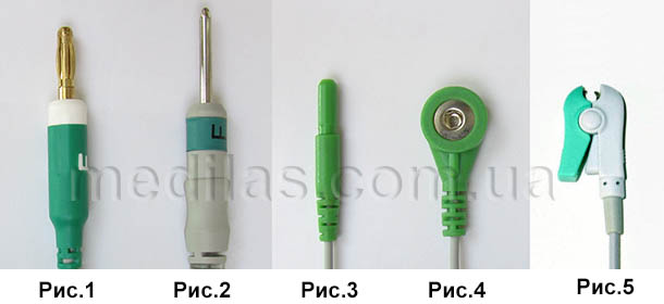
Fig.1 4 mm with "banana" spring
Fig.2 DIN 3.0 3 mm without spring
Fig.3 DIN 1.5 female
Fig.4 latch "button"
Fig.5 clamp
The contacts of the types in Fig.1 and Fig.2 have cables used with cardiographs. should fit the corresponding electrodes: chest (pegs) and limb (clothes pegs) Contacts of the types in Fig. 4 and Fig. 5 have cables used with resuscitation monitors, as well as with cardiographs as part of complexes for conducting stress tests (stress systems) They are attached to sticky disposable electrodes.
DIN 1.5 female connectors (Fig.3) have some Holter monitor cables as well as some prefabricated ECG cables.
When choosing ECG cables, please note that Ukraine has adopted the European color marking (IEC).The designation of the American marking is AHA.
Note that cables for resuscitation patient monitors come in 3-lead and 5-lead versions.
Sometimes it is also important to know if a cardiograph with a selectable cable will be used while using a defibrillator.
If you did not find the brand of your device or its type in our list, or if you have any questions, we will be happy to advise.
And, finally,
recommendations for the use of SpO2 sensors (blood oxygen saturation sensors), ECG cables, temperature sensors and other accessories
- Cable insulation can become hard and brittle when exposed to ultraviolet radiation (during treatment with germicidal lamps), as well as when treated with some disinfectants. To prevent ultraviolet radiation, we recommend covering the equipment with cables and sensors with diapers or sheets. If the cable stiffness has increased only near the electrodes, we recommend changing the disinfectant.
- Liquids must be avoided to enter the SpO2 probes (sensors). If this does happen, you should disconnect the sensor from the monitor or pulse oximeter as soon as possible and remove the liquid with a dry paper towel. Failure in such cases usually occurs not immediately, but after some time, due to the duration of the corrosion process.
- The readings of devices with SpO2 sensors can have a strong error if the sensor is worn on a finger smeared with brilliant green, iodine, and other coloring preparations. Even the painted nails of the patient can influence the indications. But it is especially bad if the dye also has time to be absorbed into the filter material. For this, the foreign manufacturer recommends that SpO2 sensors be regularly inspected and immediately discarded with signs of staining.
03 September 2014, Odessa, UKRAINE
- Details
- Hits: 1707
- You are here:
-
Home

-
Developing
-
Powerbank for uninterrupted Internet
- Uncategorised